


User Manual for BPS-4H (High Temp.)
www.levitronix.com
PL-2009-03, Rev04, DCO# 21-101
20
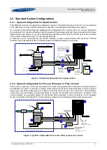
3.5 Hydraulic Circuit Design
Following general design rules for the hydraulic circuit shall be considered for a robust operation of
the pump system and optimum priming behavior:
1.
The general rule for optimum priming behavior is to minimize the pressure drop in the
inlet circuit and avoid negative pressure at the inlet of the pump head.
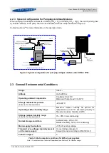
2.
Minimize tubing length at the inlet of the pump head and maximize the ID (not smaller
than the pump head inlet ID of 22.2 mm
is recommended). This reduces the pressure
drop and the tendency of cavitation.
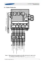
3.
Avoid any restrictions, valves, elbows, bended tubing and sharp edges at the inlet circuit
of the pump head, which potentially causes cavitation resulting in gas bubble collection
in the pump head with the danger of priming loss.
4.
Place the pump at the lowest point of the hydraulic circuit. Optimum is as much as
possible below a tank or reservoir. This optimizes priming behavior and removal of gas
bubbles.
5.
Keep the liquid level in the reservoir tank or bag as high as possible, which increases
the inlet pressure of the pump head and minimized heat up of the liquid.
6.
In general, the pump system placement and circuit shall be designed in a way that gas
bubbles can leave the pump housing and that the pump head remains primed.
7.
To minimize heat up of the liquid the overall pressure drop in the hydraulic circuit shall
be reduced as much as possible.
8.
It shall be avoided to pump longer times against a closed valve, which can cause heat-
up of the liquid.
9.
At higher liquid temperature above rules become more important due to higher cavitation
tendency of the liquid.
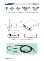
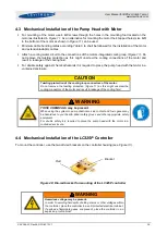
10.
Load and stress at the inlet and outlet by heavy tubing and inexact mounting alignment
shall be avoided (see
) as this can cause leakage issues due to distortion of
the plastic pump housing.
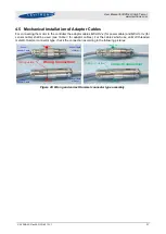
Figure 23: Avoidance of stress forces and torques at the inlet and outlet of the pump head
Contact the
Levitronix
®
Technical Service
department (see
Section 8
) for more detailed
considerations and support on the design of the hydraulic circuit.
Force/torque stress
at the in- and outlet
of the pump housing!
Tubing fixation/support to avoid
load at in- and outlet of pump system.
Pump
Heavy tubing at
in- and outlet of pump