


User Manual for BPS-4H (High Temp.)
www.levitronix.com
PL-2009-03, Rev04, DCO# 21-101
24
4.2 Electrical Installation of the PLC-A PLC-Interface Module
4.2.1 Overview
To operate the pump system in the standard configuration with a PLC, a minimum set of two digital inputs and
one analog input is needed. The digital and analog outputs can be used to monitor the pump status and
operating parameters.
CAUTION
The analog inputs and outputs are not galvanically isolated from
the controller electronics. To avoid ground loops and mal-
functions, use floating analog signals.
I/O
Specifications
2x Analog Input
Analog current input: 4
– 20 mA
Direct connection, no galvanic isolation
Input resistance: R
IN
= 450
2x Analog Output
Analog voltage output: 0
– 5 V
Direct connection, no galvanic isolation
Max. output current: 10 mA
3x Digital Input
Galvanic isolation with optocoupler
Switching voltage / current:
Minimal 10 V / 7 mA, typical 24 V / 16 mA, maximal 30 V / 20 mA
Input resistance: R
IN
= 2.2 k
3x Digital Output
Galvanic isolation (relay)
Relay: 1 A / 30 VDC, 0.3 A / 125 VAC
Table 10: Electrical specifications of the PLC-A.1 interface module
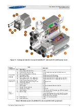
Figure 27: Standard configuration of the PLC-A.1 interface module with firmware S4.48
(For other configuration refer to corresponding firmware documentation)
Levitronix
Controller
PLC-Interface Module
Analog and Digital
Signals from User
violet-
brown+
blue+
yellow/red+
white+
red/blue -
red/blue -
red/blue -
green/brown -
pink -
turquoise-
red+
red+
red+
black-
Analog In1
Ground Analog In1
Analog In2
Ground Analog In2
Analog Out1
Common Ground Analog Out
Analog Out2
Common Ground Analog Out
Digital In1
Common Ground Digital In
Digital In2
Common Ground Digital In
Digital In3
Common Ground Digital In
Digital Out1
Common Relay Contact
Digital Out2
Common Relay Contact
Digital Out3
Common Relay Contact
Digital Out
gray-
black-
green+
10 - 30V
Optocoupler
Reference Value
Actual Speed
Reset
Process Mode
Enable
Status
Error
Warning
450 Ω
Shunt
0 - 5V
Low Pass
1A / 30VDC
0.3A / 125VAC
Relay
U
s
e
r
In
te
rf
a
c
e
C
o
n
n
e
c
to
r
o
f
L
e
v
it
ro
n
ix
C
o
n
tr
o
ll
e
r
Digital Output
Digital Input
Analog
Input
Analog
Output
Analog
Output
Analog
Input
Digital Output
Digital Output
Digital Input
Digital Input
Actual Process
Control Value
Actual Process
Control Value