


User Manual for BPS-4H (High Temp.)
www.levitronix.com
PL-2009-03, Rev04, DCO# 21-101
8
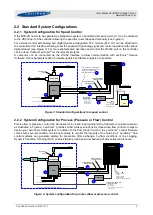
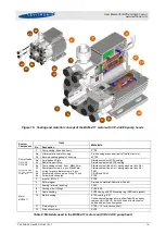
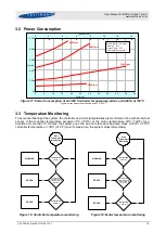
2.4 System Electronics
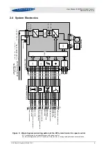
Figure 6: Block diagram and wiring pattern of the BPS-4 electronics for speed control
- PLC configuration for standard firmware with speed control
- For other configurations of PLC Inputs and Outputs refer to corresponding firmware documentation
D
S
P
D
/A
A/D
R
S
2
3
2
2
3
5
1
15
5
3
10
14
8
4
13
9
6
7
11
12
2
1
b
ro
w
n
+
vi
o
le
t
-
o
ra
n
g
e
+
gr
ay
-
b
la
ck
-
g
re
e
n
+
red
/b
lue
-
b
lu
e
+
w
h
ite
+
ye
llo
w
/r
e
d
+
ye
llo
w
+
g
re
e
n
/b
ro
w
n
p
in
k
tu
rq
u
o
ise
re
d
Ref
e
re
n
c
e
V
a
lu
e
/
A
n
a
lo
g
I
n
1
Act
u
a
l
P
ro
c
e
s
s
Co
n
tr
o
l
V
a
lu
e
/
An
a
lo
g
I
n
2
Act
u
a
l
S
p
e
e
d
/
An
a
lo
g
O
u
t1
Act
u
a
l
P
ro
c
e
s
s
Co
n
tr
o
l
V
a
lu
e
/
An
a
lo
g
O
u
t2
.
Res
e
t
/
Di
g
it
a
l
In
1
P
ro
c
e
s
s
M
o
d
e
/
Di
g
it
a
l I
n
2
E
n
a
b
le
/
Di
g
it
a
l
In
3
S
ta
tu
s
/
Dig
it
a
l
Ou
t1
E
rr
o
r /
Dig
it
a
l
Ou
t2
W
a
rn
in
g
/
Di
g
it
a
l
Ou
t3
Gr
o
u
n
d
An
a
lo
g
I
n
1
Gr
o
u
n
d
A
n
al
o
g
I
n
2
C
o
m
m
o
n
Gr
o
u
n
d
D
ig
it
al
In
Co
m
m
o
n
Re
la
y
Co
n
ta
c
t Di
g
it
a
l
Ou
t
Co
m
m
o
n
G
ro
u
n
d
An
a
lo
g
O
u
t
S
h
ie
ld
4
5
0
Ω
4
-2
0
m
A
0
-5V
10
-2
4
V,
1
0
mA
1
A
/
3
0
VD
C
0
.3
A
/
1
2
5
VAC
T
X
RX
GND
5V
1
x
A
C 2
3
0
V
10%
L
,
N
(L
1
,
L
2
)
3x
AC 208V
10%
L
1,
L
2,
L
3
M
in
im
u
m
g
a
g
e
w
ir
e =
A
W
G
1
8
(
=
1
.0
2
m
m
)
PE
4~
LP
C
ontr
ol
le
r
LC
3
2
5
P
LC
-I
nt
e
rf
a
c
e
-M
odul
e
A/D
P
o
si
ti
o
n
S
e
n
so
rs
M
15
8
M
ot
or B
SM
-4
DC
A
C
PE
L
,
N (
L
1
,
L
2
)
or
L
1
,
L
2
,
L
3
DC
3
2
5
V
10%
or
D
C
29
4V
10%
F
ilter
F
u
se
f
o
r a
ll p
o
w
e
r
line
s
u
s
e
o
n
ly
U
L
L
is
te
d
F
u
s
e
UL
ca
t.
JDY
X
10A
/
2
5
0
V
s
lo
w
i
f
L
C32
5
i
s u
se
d
1
6
A
/
2
5
0
V
s
lo
w
i
f
L
C32
5
P
i
s u
s
e
d
P
ro
te
cti
v
e
e
a
rth