


User Manual for BPS-4H (High Temp.)
www.levitronix.com
PL-2009-03, Rev04, DCO# 21-101
25
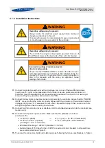
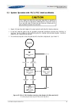
4.2.2 Installation Instructions
!
WARNING
Hazardous voltage may be present.
Always isolate the electrical power supply before making or
changing connections to the unit.
1.
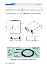
Make sure the
PLC-Interface Module
is not connected to the controller.
2.
Connect the digital and analog inputs and outputs according to
and
Assignment and functions of the I/Os can be changed with the controller firmware version (refer
to according firmware documentation).
3.
Connect the D-SUB connector of the
PLC-Interface Module
to the controller.
Wire name
Wire
color
Designation
Levels
Note
Analog In1, (Signal)
Brown
Ref Value
4..20 mA = 0..10000
rpm (speed mode)
4..20 mA = 0..100%
(process mode)
Limit is 6500 rpm = 14.4 mA
Ground Analog In1
Violet
Analog In2, (Signal)
Orange
Actual Process
Control Value
4..20 mA = 0..100%
--
Ground Analog In2
Gray
Analog Out1,
(Signal)
Yellow
Actual Speed
0..5 V = 0..10000 rpm
Direct connection, no
protection. Galvanic isolation
on the user side is required.
Analog Out2,
(Signal)
Green
Actual Process
Control Value
0..5 V = 0..100%
Direct connection, no
protection. Galvanic isolation
on the user side is required.
Common Ground
Analog Out
Black
--
--
--
Digital In1, (Signal)
Blue
Reset
24
V
active
0
V
not active
Resets fault state
Digital In2, (Signal)
Yellow /
Red
Process mode
24
V
active
0
V
not active
Switches between process
mode and speed mode
Digital In3, (Signal)
White
Enable
24
V
active, system on
0
V
not active, system off
The Enable signal switches
the pump system on and off.
Common Ground
Digital In
Red / Blue
--
--
--
Digital Out1
Green /
Brown
Status
Relay closed
active, system on
Relay open
not active, system off
This signal indicates the state
of the pump system.
Digital Out2
Pink
Error
Relay closed
not active, system on
Relay open
active, system off
When active, the system
drives the impeller to zero rpm
and shuts down. With a reset
pulse the system can be re-
initialized.
Digital Out3
Turquoise
Warning
Relay closed
not active, system o.k.
Relay open
active, system not o.k.
The warning signal indicates if
a system fault has been
detected. The warning signal
indicates a system fault but
the system does not shut
down
Common Relay
Contact Digital Out
Red
--
--
--
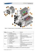
Table 11: Signals of the PLC-A.1 PLC-interface module for standard firmware
(For other configurations of PLC Inputs and Outputs refer to alternate firmware documentation.)