TO INSTALL:
NOTE:
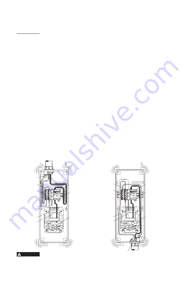
Leviton EDSR Switches may be mounted for Top or Bottom feed of supply wires
(refer to
Figures 2 and 3)
.
MOUNTING:
WARNING:
TO AVOID FIRE, SHOCK, OR DEATH;
TURN OFF POWER
AT THE CIRCUIT
BREAKER OR FUSE, AND TEST THAT THE POWER IS OFF BEFORE ATTEMPTING TO
INSTALL ENCLOSURE.
CAUTION:
THESE ENCLOSURES MUST ALWAYS BE MOUNTED VERTICALLY WITH
RECEPTACLE END DOWN.
Note:
Hinged cover will open only when the rotary switch knob is turned to the
“OFF”
position.
1.
Remove the six (6) #10-32 x 1-1/4" cover mounting screws, and rotate the hinged cover open
(refer to Figure 1)
.
2.
Determine if the installation is “top” or “bottom” feed.
3.
Drill appropriate hole size for conduit hub
(not included)
as indicated below in one of the four
drill points indicated on the top and bottom of enclosure base. Drill points provided for top left,
top right, bottom left and bottom right conduit entry
(see Conduit Hub Mounting)
.
Enclosure Mounting Using Mounting Feet:
1.
Orient mounting feet as desired
(refer to Figures 2, 3)
and secure to the enclosure base with
the provided mounting screws #10-32 x 1-1/4". Torque to 10 - 12 in.-lbs (1.2 N-m).
Conduit Hub Mounting (Conduit Hub not included):
1.
Route wires. Install 3/4" or 1" hub
(not included)
to conduit and enclosure. For 3/4" hub,
drill a 1-1/16" mounting hole. For a 1" hub, drill a 1-5/16" mounting hole. Ensure that the
"O" ring seats on the enclosure base outside wall. Install grounding bracket and secure
tightly with hub nut.
2.
Secure enclosure to the desired surface. Mounting hardware accept up to a 1/4" diameter
screw
(not included)
.
3.
Make connections as per wiring instructions.
3
To “G” Term.
of Rcpt.
To “W” Term.
of Rcpt.
Neutral
Buss
Ground
Buss
Rotary
Switch
Auxiliary
Contact
Mounting Feet (4)
Listed Conduit Hub (not supplied)
Type 3R, 4X, 12K Rated
Ground
Bracket
Receptacle
(not supplied)
Condensation
Drip Loops
To “G” Term.
of Rcpt.
To “W” Term.
of Rcpt.
Neutral
Buss
Ground
Bracket
Listed Conduit Hub
(not supplied)
Type 3R, 4X, 12K Rated
Receptacle
(not supplied)
Mounting Feet (4)
Ground
Buss
Rotary
Switch
Auxiliary
Contact
Figure 2
Top Conduit
Connection/Wire Entry
Figure 3
Bottom Conduit
Connection/Wire Entry
CAUTION
THESE ENCLOSURES MUST ALWAYS
BE MOUNTED VERTICALLY WITH
RECEPTACLE END DOWN.
Summary of Contents for PowerSwitch EDSR
Page 11: ...NOTES ...


