background image

4

LEVEL Ltd.

Contents

1.

Description and Features …………………………………………………… 5
1.1.

Description of the GB 060 515C Car Alarm Unit………………….. 5

1.2.

Recommended Set and Connections .............…………………….. 6

1.3.

Standard Set and Optional Accessories ………….…………..……. 7

1.4.

Summary Table of GSM Alarms and Messages ...………………… 7

1.5.

Access Card Features ………………...……………………………… 8

1.6.

Emergency Button Features …………………………………………. 8

1.7.

Signalization LED in Vehicle ...........………………………………… 8

1.8.

GPRS for Online Electronic Log Book of Rides ......……………….. 9

1.9.

Navigation ...........……………………………………………………… 9

2.

Operation, Configuration ……………………………………………………… 9
2.1.

Quick Start ……………………………………………………………. 9

2.2.

Configuration and Operation - SMS Commands Table .………… 10

2.3.

What to do when something doesn’t work ..………………………. 14

3.

Installation ……………………………………………………………………. 14
3.1.

Condition for Use, Safety …………………………………………… 14

3.2.

Connections Drawing ……………………………………………….. 15

3.3.

Hints for installation …………………………………………………. 16

3.4.

Checking Functionality ………………………………………………. 17

4.

Technical parameters, Maintenance ………………………………………. 18
4.1.

Technical parameters …………………………………………………18

4.2.

Maintenance ..………………………………………………………… 21

Warranty Conditions ………………………………………………………………. 21
Warranty Certificate ..……………………………………………………………….22

Summary of Contents for GB 060 515 C

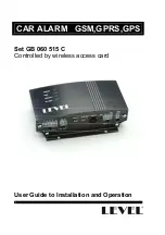
Page 1: ...CAR ALARM GSM GPRS GPS Set GB 060 515 C Controlled by wireless access card User Guide to Installation and Operation...

Page 2: ...2...

Page 3: ...f vehicle by sending SMS command when speed decreases under 10 km h Listening and voice call to vehicle cabin to discourage robbers for communication with crew or to detect false alarms Navigation for...

Page 4: ...ion LED in Vehicle 8 1 8 GPRS for Online Electronic Log Book of Rides 9 1 9 Navigation 9 2 Operation Configuration 9 2 1 Quick Start 9 2 2 Configuration and Operation SMS Commands Table 10 2 3 What to...

Page 5: ...5 1 Description and Features 1 1 Description of the GB 060 515C Car Alarm Unit...

Page 6: ...6 1 2 Recommended Sets and Connections...

Page 7: ...microphone Active loudspeakers Cable RS 232 from GB060 to a PC Reduction RS 232 from GB060 to a PDA 1 4 Summary Table of GSM Alarms and Messages Alarm description SMS Text Ringing Tel1 Tel2 Tel3 Tel4...

Page 8: ...ay will close LED will stop blinking Press the two buttons oo and o o on cooperating card at the same time hold them for about 8 seconds LED on ID card must blink quickly for 4 seconds Within 10 secon...

Page 9: ...igation software For connection with a laptop use cable CB 160 021 For connection with a PDA use cable CB 160 021 and reduction CB 160 017 2 Operation Configuration 2 1 Quick Start Inserting SIM card...

Page 10: ...of settings space marked as _ in text PARAMETER value or some commands have no parameter One SMS can contain up to 4 commands with parameters PIN_command1_parameter1_command2_parameter2_command3_para...

Page 11: ...dioin_x audioin_x 0 lowest volume to 100 75 Inquiry SMS Reply Value x pin_audioin_ audioin_x 0 lowest volume to 100 Volume of loudspeaker with amplifier Settings SMS Reply Value x Set to x pin_audioou...

Page 12: ...phone display Disabling alarm Settings SMS Reply pin_servon servon Run Canceling SMS Reply pin_servoff servoff Run Disabling alarm until next ride ignition on Short press of emergency button less than...

Page 13: ...the car cabin To use this feature no loudspeaker should be installed GPS localization SMS Reply Value x Value y pin_gpsd gpsd_x_y Coordinates in format 50 402706 N Coordinates in format 16 145190 E In...

Page 14: ...tion SMS Message will be sent automatically each Monday at 10 am it is necessary to set correct time and date in unit Pressing the INIT button on unit installed in car for more than 5 seconds with con...

Page 15: ...nnection to 12 V must be protected by a 5 A safety fuse Disconnect the negative power supply pole of battery be careful with car radio codes It is recommended to install sensors first and then make co...

Page 16: ...e 7 mm drill ED 060 605 Alarm siren Install in upper parts by the engine point the output to the ground ED 060 620 Wireless access card receiver Bundle with cables near the car alarm unit ED 060 619 U...

Page 17: ...turn on the internal battery power supply by pressing the INIT button on car alarm unit 3 4 Checking Functionality Start the car alarm unit as described in chapter Quick start Checking external and i...

Page 18: ...all sensors for three minutes Create audio communication with callback and make volume settings for loudspeaker and sensitivity settings for microphone See table of SMS commands Erase the testing phon...

Page 19: ...to connection with frame Input 3 Input from motion sensor ultrasonic microwave Parallel connection to hood sensor Reacts to connection with frame Input 4 Emergency button Long press over 1 5 second e...

Page 20: ...ures for GSM 25 C to 55 C Temperatures for rest of unit 40 C to 85 C LED signalization of car alarm POWER Off Permanently on Blinks 1 2s 0 2s Blinks 0 2s 1 2s Blinks 0 2s 0 2s No external power supply...

Page 21: ...working days after delivery of faulty unit to LEVEL provided all spare parts are in stock If not the customer will be offered an alternative solution Warranty repairs will be carried out in the manufa...

Page 22: ...22 Warranty Certificate Product name Type Serial number Date of sale Seller Address phone number stamp Signature Received for repair Date of shipping Fault description...

Page 23: ...23...

Page 24: ...24 GB 060 515 C1 Version 1 02 LEVEL 2006 LEVEL Ltd Plhovsk 1997 N chod 547 01 E mail level levelna cz Website www levelna cz...

Reviews: