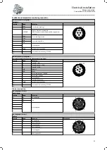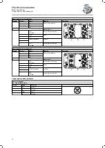
Feedback and temperature monitoring connection
ICN-M23 connector assignment
Resolvers
Contact
Name
Meaning
1
+ Ref
Transformer windings
1
2
3
4
5
6
7
8
9
10
11
12
P
Code 0°
2
- Ref
3
+VCC ENP
Supply: Electronic nameplate
(Only for motors and inverters which support this
function)
4
+ Cos
Stator windings cosine
5
- Cos
6
+ Sin
Stator windings Sine
7
- Sin
8
Not assigned
9
10
Shield
Encoder housing shield
11
+
Temperature monitoring: PT1000
12
-
ICN-M23 connector assignment
Incremental and SinCos absolute value encoder Hiperface©
Contact
Name
Meaning
1
B
Track B / + SIN
1
2
3
4
5
6
7
8
9
10
11
12
P
Code 20°
2
A¯
Track A inverse / - COS
3
A
Track A / + COS
4
+ UB
5
GND
Mass
6
Z¯
Zero track inverse / - RS485
7
Z
Zero track / + RS485
8
Not assigned
9
B¯
Track B inverse/-SIN
10
Shield
Encoder housing shield
11
+
Temperature monitoring: PT1000
12
-
Blower connection
Pin assignment ICN-M17
Single−phase
Contact
Name
Meaning
PE
PE
PE conductor
1
4
2
5
6
3
+
1
U1
Fan
2
U2
3
Not assigned
4
5
6
Pin assignment ICN-M17
3-phase
Contact
Name
Meaning
Illustration
PE
PE
PE conductor
1
4
2
5
6
3
+
1
V
Power phase U
2
Not assigned
3
V
Power phase V
4
Not assigned
5
6
W
Power phase W
Electrical installation
Motor connection
Connection via ICN connector
29

