background image

Diagnostics and fault elimination

Malfunctions

If faults occur during the operation of the drive, the table below helps you to identify the

causes. If it is not possible to remedy the fault using the measures listed, please contact the

Lenze service department.

Error

Possible causes

Remedy

Motor too hot
 
Can only be evaluated by measuring the surface
temperature:

Non-ventilated motors >140 °C

Externally ventilated or self-ventilated motors
> 110 °C

Insufficient cooling air, blocked air ducts.

Ensure unimpeded circulation of cooling air

Preheated cooling air

Ensure a sufficient supply of fresh cooling air

Overload, with normal mains voltage the
current is too high and the speed too low

Use larger drive (determined by power
measurement)

Rated operating mode (S1 to S8 IEC/EN
60034-1) exceeded

Adjust rated operating mode to the specified
operating conditions. Determination of correct
drive by expert or Lenze customer service

Loose contact in supply cable (temporary
single-phase operation!)

Tighten loose contact

Fuse has blown (single-phasing!)

Replace fuse

Overload of the drive

Check load and, if necessary, reduce by means
of longer ramp-up times
Check winding temperature

Heat dissipation impeded by deposits

Clean surface and cooling fins of the drives

Motor suddenly stops and does not restart

Overload monitoring of the inverter is activated Check inverter settings

Reduce load caused by longer acceleration
times

Incorrect direction of rotation of the motor,
correct display on the inverter

Motor cable with reverse polarity

Check and correct polarity

Polarity of encoder cable reversed

Motor rotates normally but does not reach the
expected torque

Motor cable interchanged cyclically
Not all motor phases connected

Connect the phases at the motor cable
connection correctly

Motor turns in one direction at maximum speed
in an uncontrolled manner

Motor cable interchanged cyclically

Check motor connection and, if necessary,
correct

Polarity of encoder cable reversed

Check encoder connection and, if necessary,
correct

Motor slowly rotates in one direction and is not
influenced by the inverter

Polarity of motor cable and encoder cable
reversed

Check and correct polarity

Irregular running

Insufficient shielding of motor or resolver cable Checking shielding and earth connection
Inverter gain too large

Adjust the gains of the controllers (see
operating instructions for the inverter)

Vibrations

Insufficiently balanced coupling elements or
machine

Rebalance

Inadequate alignment of drive train

Realign machine unit, check foundation, if
necessary.

Loose fixing screws

Check and tighten screw connections

Running noises

Foreign particles inside the motor

Repair by the manufacturer, if necessary

Bearing damage

Surface temperature > 140 °C

Overload of the drive

Check load and, if necessary, reduce by means
of longer ramp-up times.
Check winding temperature

Heat dissipation impeded by deposits

Clean surface and cooling fins of the drives.

Diagnostics and fault elimination

Malfunctions

40

Summary of Contents for IE2 m550-H

Page 1: ...Three phase AC motors IE2 three phase AC motor m550 H Version B IE3 three phase AC motor m550 P Version B Mounting and switch on instructions EN...

Page 2: ......

Page 3: ...llation 17 Important notes 17 Transport 17 Preparation 17 Installation 18 Dimensions 18 Mounting 19 Product extensions 20 Electrical installation 22 Important notes 22 Preparation 22 Motor connection...

Page 4: ...nd operating conditions 42 Conformities and approvals 42 Protection of persons and device protection 42 EMC data 42 Environmental conditions 43 Rated data 44 Ecodesign directive 50 Environmental notes...

Page 5: ...her with the complete documentation of the product For safety rated attachments observe the enclosed operating instructions of the manufacturer The document includes safety instructions which must be...

Page 6: ...er documentation with additional information Example EDKxxx see documentation EDKxxx Layout of the safety instructions DANGER Indicates an extremely hazardous situation Failure to comply with this ins...

Page 7: ...personal injury and damage to property Observe all specifications of the corresponding documentation supplied This is the precondition for safe and trouble free operation and for obtaining the product...

Page 8: ...ucts comply with the applicable national accident prevention regulations The electrical installation work must be carried out according to the appropriate regulations e g cable cross sections fusing P...

Page 9: ...utting into operation as intended is only permitted in compliance with the EMC Directive 2014 30 EU The product is not a household appliance Instead it is a component that is intended exclusively for...

Page 10: ...s The product does not provide any safety related functions A higher level safety system must be implemented Provide additional monitoring and protective equipment complying with the safety regulation...

Page 11: ...ds of operation with I Irated especially if there is a danger of blocking The integrated overload protection does not prevent overloading under all conditions The fuses are no motor protection Use a c...

Page 12: ...Position Shaft flange terminal box motec 16 2 Supply voltage 6 5 Mounting position 16 3 Power 6 6 Lubricant 16 4 Braking torque 6 7 Lubricant quantity 17 Blower 7 Motor data 17 1 Rated voltage 7 1 Pr...

Page 13: ...er of poles 4 pole 04 Degree of protection IP54 IP55 5 IP65 IP66 6 Cooling Self ventilation E Forced ventilation F Brake Without 0 Spring applied brake F Feedback Without 0 Absolute value encoders A I...

Page 14: ...ree phase AC motors 1 Number of pole pairs for resolvers 2 3 4 Number of steps increments per revolution 20 32 128 512 1024 2048 Supply voltage 5V 8V 15V 24V Interface or signal level Standard TTL T H...

Page 15: ...ides an overview of the elements and connections on the product Their position size and appearance may vary Foot Output flange Output shaft Brake Motor connection Cooling Feedback Temperature monitori...

Page 16: ...sible in the manufacturer s packaging In dry low vibration environment without aggressive atmosphere Protect against dust and impacts Observe the climatic conditions according to the technical data 4E...

Page 17: ...uments Secure the load against tipping and falling down Standing beneath suspended loads is prohibited The transport weights can be found in the shipping documents Preparation Protect shaft sealing ri...

Page 18: ...ited to absorb the forces and torques generated during operation Ensure an unhindered ventilation For versions with a fan keep a minimum distance of 10 from the outside diameter of the fan cover in in...

Page 19: ...led manner according to manufacturer information Be sure to carry out mounting in a manner free from distortion Compensate minor inaccuracies by suitable flexible couplings Fastening Use screws with a...

Page 20: ...the terminal block 3 over the manual release lever 4 3 Guide the manual release lever with terminal block 3 4 through the slot in the fan cover 5 and screw it into the threaded hole in the manual rele...

Page 21: ...ke is released 1 4 3 5 1 1 1 Cheese head screw with hexagon nut 4 Manual release lever 3 Terminal block 5 Fan cover How to lock the manual release lever 1 Loosen hexagon nut 1 1 and cheese head screw...

Page 22: ...fore starting work When working on energized products comply with the applicable national accident prevention regulations The electrical installation must be carried out according to the appropriate r...

Page 23: ...nect the motor correctly you must follow The notes in the terminal box of the motor The notes in the configuration document of the motor The technical data on the motor nameplate Electrical installati...

Page 24: ...dirt and humidity All unused cable entries and the terminal box itself must be sealed so that they are dust tight and waterproof The smallest air gaps between uncoated live parts and against earth mu...

Page 25: ...6 Tightening torques 10 Nm 2 2 3 5 4 5 Cable glands position 2 Cable glands M12x1 5 M16x1 5 M20x1 5 M25x1 5 M32x1 5 M40x1 5 M50x1 5 Tightening torques 10 Plastics Nm 0 7 1 0 1 0 2 5 3 0 3 0 3 0 Metal...

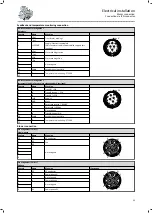
Page 26: ...witching Feedback connection Resolver Contact Name Meaning B1 Ref Transformer windings reference windings B2 Ref B3 VCC ETS Power supply electronic nameplate Only for model with electronic nameplate E...

Page 27: ...Contact Name Meaning TB1 Thermal contact TCO TB2 1TP1 PTC thermistor 150 1TP2 2TP1 PTC thermistor 130 2TP2 R1 Thermal detectors PT1000 R2 Thermal detectors PT1000 Blower connection 1 phase Contact Na...

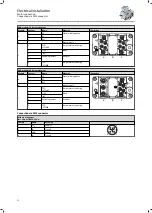
Page 28: ...terminal box can be rotated step by step by 90 after loosening the screws in the terminal box Power and brake connection ICN M23 connector assignment 6 pin Contact Name Meaning 1 BD1 DC AC holding br...

Page 29: ...Hiperface Contact Name Meaning 1 B Track B SIN 1 2 3 4 5 6 7 8 9 10 11 12 P Code 20 2 A Track A inverse COS 3 A Track A COS 4 UB Supply 5 GND Mass 6 Z Zero track inverse RS485 7 Z Zero track RS485 8 N...

Page 30: ...s due to incorrect mounting Malfunctions may occur ICN connector with screwed connection Do not remove O ring ICN connector with SpeedTec bayonet lock remove O ring and dispose of it 1 1 When connecti...

Page 31: ...oring Additionally for HAN Modular Rectifier connection HAN 10E connector The motor connection is specified in the counter plug The connector is only suitable for motors with the connection method Y B...

Page 32: ...A pin assignment Module Contact Name Meaning Illustration a 1 U1 Motor winding phase 4 5 6 3 2 1 1 2 3 4 5 6 3 2 1 a c a b c 2 V1 3 W1 b Blank module c 1 TCO PT1000 Temperature monitoring 2 AC Brake...

Page 33: ...viscosity of the roller bearing grease Take a starting torque reserve for the motor of around 20 into account during the configuration Commissioning at over 10 C Operate the drive with max 50 of the...

Page 34: ...aces that can get hot Is the contact of good electrical conductivity if a PE connection on the motor housing is used After a long period of downtime or after overhauling the motor check the insulation...

Page 35: ...ours then every 2 years Check fastening elements Check all fixing screws on the motor foot and flange fixing for tightness Spring applied brake NOTICE A maintenance concept adapted to the operating co...

Page 36: ...er cover 3 Remove fan cover Release brake and check voltage DANGER Risk of injury due to rotary parts Do not touch rotating components DANGER Risk of injury by electric shock Do not touch live connect...

Page 37: ...e and check the air gap sL through the bore After checking push the sealing plug back in taking care not to tilt the plug 3 Measure the air gap sL between stator 1 and armature plate 2 in the vicinity...

Page 38: ...4 0 10 0 05 Application brake ABR protection class IP54 55 Brake Tightening torque Air gap sL max sL N Service brake Holding brake Nm mm mm ABR 06 3 0 0 50 0 30 0 2 0 10 0 05 ABR 08 5 9 ABR 10 10 1 A...

Page 39: ...operation of the drive system First check the possible causes of malfunction according to the 4Diagnostics and fault elimination 40 If the fault cannot be remedied using one of the measures listed pl...

Page 40: ...r acceleration times Incorrect direction of rotation of the motor correct display on the inverter Motor cable with reverse polarity Check and correct polarity Polarity of encoder cable reversed Motor...

Page 41: ...e Check wiring If AC voltage is ok Check rectifier Replace defective rectifier Check coil for interturn fault or short circuit to ground If the rectifier is repeatedly faulty replace the spring applie...

Page 42: ...o 100 CSA Standard for motors and generators only applies to 8400 motec UL 1004 1 UL Standard for Rotating Electrical Machines only applies to 8400 motec UL 1004 8 UL Standard for Inverter Duty Motors...

Page 43: ...3 2 2K3 25 70 C Operation EN 60721 3 3 3K3 0 40 C 30 10 C Depending on the temperature range Observe ambient temperature data on the nameplate 30 40 C Site altitude 0 1000 m amsl 1000 4000 m amsl Red...

Page 44: ...18 1 71 2 34 400 V Irated Y A 0 410 0 540 0 680 0 990 1 35 Starting current Ia A 1 40 1 94 2 60 4 23 6 32 Rated torque Mrated Nm 0 810 1 23 1 72 2 48 3 67 Starting torque Ma Nm 1 54 2 46 3 44 4 45 6...

Page 45: ...ertia J kgcm 27 2 53 8 58 3 123 130 3 198 Weight m kg 12 28 17 33 18 43 30 41 31 61 40 38 Motor M55BP 132M04 132L04 160M04 160L04 180M04 180L04 Rated power Prated kW 5 5 7 5 11 15 18 5 22 Rated speed...

Page 46: ...600 0 880 1 21 Starting current Ia A 1 47 2 07 2 68 4 28 6 32 Rated torque Mrated Nm 0 700 1 00 1 40 2 00 3 00 Starting torque Ma Nm 1 54 2 32 3 08 3 88 5 74 Stalling torque Mb Nm 2 01 2 83 3 78 6 94...

Page 47: ...rtia J kgcm 27 2 53 8 58 3 123 130 3 198 Weight m kg 12 28 17 33 18 43 30 41 31 61 40 38 Motor M55BP 132M04 132L04 160M04 160L04 180M04 180L04 Rated power Prated kW 5 5 7 5 11 15 18 5 22 Rated speed n...

Page 48: ...ted voltage Dreieck Vrated V 400 400 400 400 400 Rated current 400 V Irated A 0 740 0 970 1 19 1 75 2 42 Rated torque Mrated Nm 0 794 1 26 1 72 2 49 3 76 Power factor cos 0 6 0 68 0 72 0 7 0 74 Effici...

Page 49: ...J kgcm 27 2 53 8 58 3 123 130 3 198 Weight m kg 12 28 17 33 18 43 30 41 31 61 40 38 Motor M55BP 132M04 132L04 160M04 160L04 180M04 180L04 Rated power Prated kW 9 6 13 1 19 2 26 3 32 2 38 5 Rated speed...

Page 50: ...l GERMANY 5 Model number of the product M55BH 063S04 063M04 063L04 071M04 071L04 6 Number of motor poles 4 4 4 4 4 7 Rated output power in kW 0 12 0 18 0 25 0 37 0 55 8 Rated input frequency in Hz 50...

Page 51: ...motor poles 4 4 4 4 4 4 7 Rated output power in kW 0 75 1 1 1 5 2 2 3 4 8 Rated input frequency in Hz 50 50 50 50 50 50 9 Rated voltage in V 400 400 400 400 400 400 10 Rated speed in rpm 1455 1465 146...

Page 52: ...motor poles 4 4 4 4 4 4 7 Rated output power in kW 5 5 7 5 11 15 18 5 22 8 Rated input frequency in Hz 50 50 50 50 50 50 9 Rated voltage in V 400 400 400 400 400 400 10 Rated speed in rpm 1480 1480 14...

Page 53: ...European Regulation EC No 1907 2006 REACH chemical regulation When used as intended exposure of substances to humans animals and the environment is excluded Lenze products are industrial electrical a...

Page 54: ......

Page 55: ......

Page 56: ...e 3 32699 Extertal GERMANY HR Lemgo B 6478 Phone 49 5154 82 0 Fax 49 5154 82 2800 sales de lenze com www Lenze com Lenze Service GmbH Breslauer Stra e 3 32699 Extertal GERMANY Phone 0080002446877 24 h...

Reviews: