


80
Z/P Series Hardware Maintenance Manual
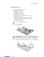
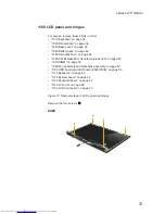
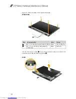
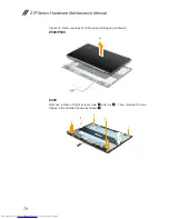
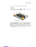
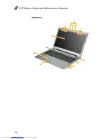
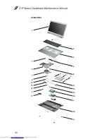
1170 Integrated camera, LCD cable and antenna assembly
For access, remove these FRUs in order:
•
“1010 Keyboard” on page 33
•
“1020 Optical drive” on page 36
•
“1030 Base cover” on page 39
•
“1040 Battery pack” on page 44
•
“1050 Hard disk drive” on page 46
•
“1060 PCI Express Mini Card for wireless LAN” on page 48
•
“1070 DIMM” on page 50
•
“1080 Fan assembly and Heat Sink assembly” on page 52
•
“1100 ODD board and LED board (Z500/P500)” on page 58
•
“1110 Speakers” on page 60
•
“1120 System board” on page 63
•
“1130 Keyboard bezel” on page 67
•
“1140 LCD unit” on page 69
•
“1150 LCD front bezel” on page 73
•
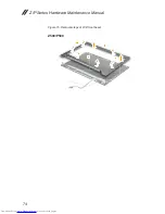
“1160 LCD panel and hinges” on page 75
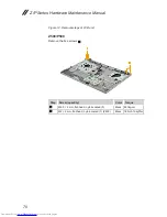
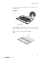
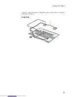
Figure 17. Removal steps of integrated camera, LCD cable and antenna
assembly
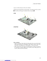
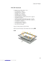
Note:
The integrated camera is stuck on the top center of the LCD cover.
Detach the integrated camera connector in the direction shown by arow
1
.
Z400
1
Summary of Contents for Z series
Page 1: ...Lenovo Z P Series Hardware Maintenance Manual ...
Page 90: ...86 Z P Series Hardware Maintenance Manual Z500 P500 3 3 1 2 4 5 6 7 8 9 10 11 ...
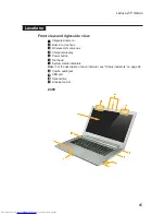
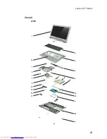
Page 93: ...89 Lenovo Z P Series Overall Z400 2 3 4 6 13 c 16 18 d a b 8 1 5 e 7 9 10 12 14 19 f 17 ...
Page 102: ...98 Z P Series Hardware Maintenance Manual 15 6 in HD TFT 1 2 3 5 4 6 7 ...