


52
Z/P Series Hardware Maintenance Manual
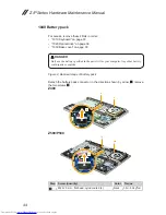
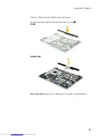
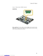
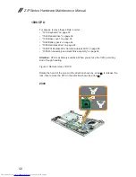
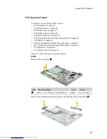
1080 Fan assembly and Heat Sink assembly
For access, remove these FRUs in order:
•
“1010 Keyboard” on page 33
•
“1020 Optical drive” on page 36
•
“1030 Base cover” on page 39
•
“1040 Battery pack” on page 44
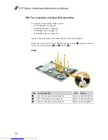
Figure 8. Removal steps of fan assembly and heat sink assembly
Detach the fan connector in the direction shown by arrow
1
, and then remove
a total of six screws (three
2
, two
3
and one
4
).
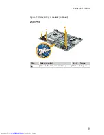
Z400
4
3
3
2
2
1
Step Screw (quantity)
Color Torque
2
M2 × 3.2, flat-head, nylok-coated (3)
Black
1.85+/-0.15 kgf*cm
3
M2 × 3, flat-head, nylok-coated (2)
Black
1.85+/-0.15 kgf*cm
4
M2.5 × 6, flat-head, nylok-coated (1)
Black
3.0+/-0.3 kgf*cm
Summary of Contents for Z series
Page 1: ...Lenovo Z P Series Hardware Maintenance Manual ...
Page 90: ...86 Z P Series Hardware Maintenance Manual Z500 P500 3 3 1 2 4 5 6 7 8 9 10 11 ...
Page 93: ...89 Lenovo Z P Series Overall Z400 2 3 4 6 13 c 16 18 d a b 8 1 5 e 7 9 10 12 14 19 f 17 ...
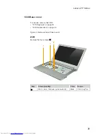
Page 102: ...98 Z P Series Hardware Maintenance Manual 15 6 in HD TFT 1 2 3 5 4 6 7 ...