© Copyright Lenovo 2019
Chapter 3: Installing NE1072T Hardware and Options
45
6.
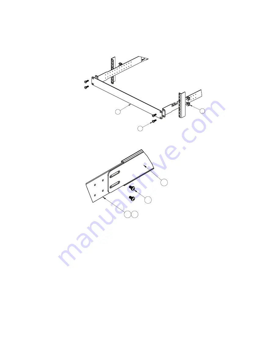
Attach the filler plate (Item 9) and rear mounting brackets to the rear rack posts
with M6 screws (Item 3), and either clip nuts (Item 4) or cage nuts (Item 5). Torque
the screws to approximately 5.7 Nm ± 0.1 Nm (50 inch-pounds).
7.
Secure the rear brackets to the front brackets with M3.5 screws (Item 6). Torque the
screws to approximately 0.5 Nm (4 inch-pounds).
8.
If installing the 1U air-duct option, see the instruction on
9.
Connect all external cables in accordance with the
10.
Initialize the switch. See
Chapter 5, “Initializing the NE1072T“
11.
If the switch is a replacement unit, set Vital Product Data (see
3
5
9
1
7
8
6
Summary of Contents for ThinkSystem NE1072T
Page 6: ...6 Lenovo NE1072T Installation Guide ...
Page 16: ...16 NE1072T Installation Guide ...
Page 56: ...56 NE1072T Installation Guide ...
Page 74: ...74 NE1072T Installation Guide ...
Page 90: ...90 NE1072T Installation Guide ...
Page 96: ...96 NE1072T Installation Guide ...
Page 112: ...112 NE1072T Installation Guide ...
Page 118: ...118 NE1072T Installation Guide ...


