© Copyright Lenovo 2018
Chapter 2: Switch Components
23
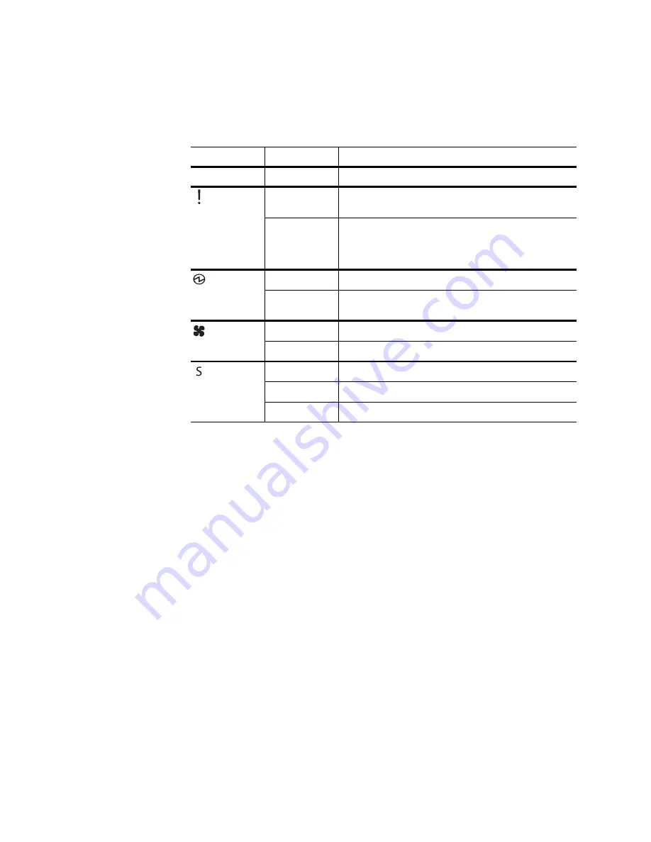
System Status LEDs
The following table describes the behavior of the system status LEDs:
Note 1:
Support for the stacking feature depends on the installed firmware. To
determine whether your switch supports stacking, see the
Application Guide
for your
specific switch and firmware version.
Note 2:
If service required is due to a stacking error, this LED flashes or is steady
green, depending on its last known good state.
USB Port
The USB port enables you to connect a USB drive to the switch. You can copy files
from the switch to the USB drive, or from the USB drive to the switch. You can also
start the switch using files on the USB drive.
The supported file system formats for USB drives are FAT32 and NTFS (read-only).
Note:
When using a NTFS formatted USB drive, copying operations are limited to
read-only. Files can be copied from the USB drive to the switch, but copying files to
the NTFS formatted USB drive results in failure.
For more information about using the USB drive, see the
Lenovo ThinkSystem
NE1032 RackSwitch Release Notes
.
Table 3.
System status LEDs behavior
LED
State
Functional Meaning
All
Off
Total power failure.
- Service
Steady blue
An operational command has been sent to light the
LED so that this device can be more readily located.
Flashing blue
Service is required due to failure of the general system,
its cooling fans, stacking function
1
or its power supply.
The specific failure is indicated in conjunction with the
other system status LEDs.
- Power
Steady green
Power is OK.
Flashing green
Power supply failure or disconnection. Service is
required.
- Fans
Steady green
Fans are OK.
Flashing green
Fan failure. Service is required.
- Stacking
1
Steady green
Device is a Backup/Member in a stack.
2
Flashing green
Device is the Master in a stack.
2
Off
Device is not a stacking member.
Summary of Contents for ThinkSystem NE1032
Page 6: ...6 Lenovo NE1032 Installation Guide ...
Page 14: ...14 NE1032 Installation Guide ...
Page 18: ...18 NE1032 Installation Guide ...
Page 30: ...30 NE1032 Installation Guide ...
Page 86: ...86 NE1032 Installation Guide ...
Page 92: ...92 NE1032 Installation Guide ...
Page 112: ...112 NE1032 Installation Guide ...


