


A checkpoint code (See checkpoint code display
1
) is either a byte or a word
value produced by UEFI and sent to the I/O port indicating the point at which the
system stopped during the boot block and Power-On Self Test (POST). It does not
provide error codes or suggest replacement components. These codes can be used
by Lenovo Support for more in depth troubleshooting.
v
Remind button:
This button places the system-error LED on the front panel into
Remind mode. In Remind mode, the system-error LED flashes once every 2
seconds until the problem is corrected, the system is restarted, or a new problem
occurs.
By placing the system-error LED indicator in Remind mode, you acknowledge
that you are aware of the last failure but will not take immediate action to correct
the problem. The remind function is controlled by the IMM.
v
NMI button:
Press this button to force a nonmaskable interrupt to the
microprocessor, if directed to do so by service and support.
v
Check-point code display:
During POST, this display indicates server firmware
progress. The display does not provide error codes or suggest components to be
replaced. Checkpoint codes can be used by Lenovo Support for further
troubleshooting. See the
Hardware Maintenance Manual
for more information
about checkpoint codes.
There are two types of checkpoint codes: field programmable gate array (FPGA)
hardware checkpoint codes and UEFI checkpoint codes. The UEFI checkpoint
codes might change because of code sequence and timing changes or when the
server firmware is updated.
v
Reset button:
Press this button to reset the server and run the power-on
self-test (POST). You might have to use a pen or the end of a straightened paper
clip to press the button. The reset button is in the lower right-hand corner of the
diagnostics panel.
For more information about EasyLED diagnostics, see the
Hardware Maintenance
Manual
.
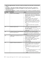
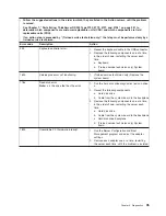
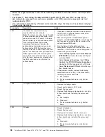
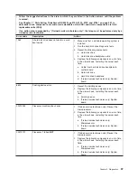
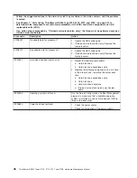
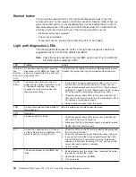
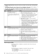
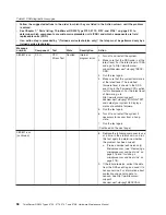
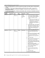
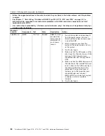
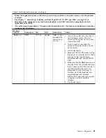
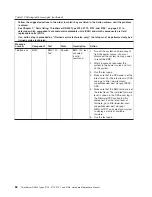
The following table lists the LEDs on the EasyLED diagnostics panel and suggested
actions to solve the detected problems.
v
Follow the suggested actions in the order in which they are listed in the Action column until the problem
is solved.
v
See the parts listing in the
Hardware Maintenance Manual
to determine which components are customer
replaceable units (CRU) and which components are field replaceable units (FRU).
v
If an action step is preceded by “(Trained service technician only),” that step must be performed only by a
trained service technician.
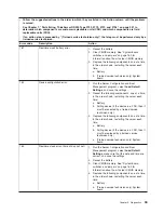
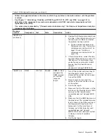
LED
Description
Action
None, but
the
system-
error LED
is lit.
An error has occurred and cannot be
diagnosed, or the IMM has failed. The
error is not represented by an EasyLED
diagnostics LED.
Use the Setup utility to check the system-event log for
information about the error.
Chapter 5. Diagnostics
47
Summary of Contents for THINKSERVER 3729
Page 1: ...Hardware Maintenance Manual ThinkServer RD220 Types 3797 3798 3779 and 3729 ...
Page 2: ......
Page 3: ...ThinkServer RD220 Types 3729 3779 3797 and 3798 Hardware Maintenance Manual ...
Page 8: ...vi ThinkServer RD220 Types 3729 3779 3797 and 3798 Hardware Maintenance Manual ...
Page 156: ...148 ThinkServer RD220 Types 3729 3779 3797 and 3798 Hardware Maintenance Manual ...
Page 238: ...230 ThinkServer RD220 Types 3729 3779 3797 and 3798 Hardware Maintenance Manual ...
Page 264: ...256 ThinkServer RD220 Types 3729 3779 3797 and 3798 Hardware Maintenance Manual ...
Page 265: ......
Page 266: ...Part Number 40M2493 Printed in USA 1P P N 40M2493 ...


