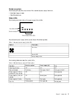


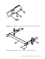


3. Loosen and remove M6 washers, screws, and clip nuts that attach the filler plate to the rear mounting
brackets.
4
2
6
8
4. Slide the rear mounting brackets out of the slots available on the front mounting brackets.
.
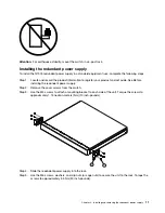
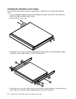
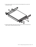
Installing and removing the redundant power supply
17
Summary of Contents for RackSwitch G7000
Page 1: ...Lenovo RackSwitch G7000 Redundant Power Supply Installation Guide ...
Page 8: ......
Page 14: ...6 Lenovo RackSwitch G7000 Redundant Power Supply Installation Guide ...
Page 28: ...20 Lenovo RackSwitch G7000 Redundant Power Supply Installation Guide ...
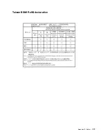
Page 37: ...Taiwan BSMI RoHS declaration Appendix B Notices 29 ...
Page 38: ...30 Lenovo RackSwitch G7000 Redundant Power Supply Installation Guide ...
Page 41: ......
Page 42: ......


