background image

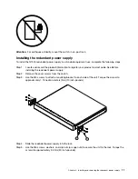
Installing the redundant power supply

To install the redundant power supply in a Lenovo System x or IBM Power rack, complete the following 
steps:  

1.  Locate and record the product information to configure and register your product and set aside. See 

Before installing the redundant power supply.

2.  Remove the rear cover screws. 

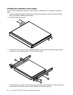
3.  Use the M4 screws to attach the front mounting brackets to each side of the redundant power supply. 

Torque the screws to approximately 1.13 Nm (10 inch-pounds). 

 7 

1

 9 

 9 

4.  Use the M6 screws, washers, and clip nuts to connect the front mounting brackets to the front and rear 

posts in the rack. Torque the screws to approximately 3.5 Nm (30 inch-pounds). 

14

Lenovo RackSwitch G7000 Redundant Power Supply Installation Guide

Summary of Contents for RackSwitch G7000

Page 1: ...Lenovo RackSwitch G7000 Redundant Power Supply Installation Guide ...

Page 2: ...the Warranty Information document that comes with your power supply option Second Edition October 2017 Copyright Lenovo 2015 2017 LIMITED AND RESTRICTED RIGHTS NOTICE If data or software is delivered pursuant to a General Services Administration GSA contract use reproduction or disclosure is subject to restrictions set forth in Contract No GS 35F 05925 ...

Page 3: ...ix A Getting help and technical assistance 21 Before you call 21 Using the documentation 22 Getting help and information from the World Wide Web 22 Software service and support 22 Hardware service and support 22 Taiwan product service 22 Appendix B Notices 23 Trademarks 24 Important notes 24 Particulate contamination 24 Telecommunication regulatory statement 25 Electronic emission notices 25 Feder...

Page 4: ...erer dette produkt Lees voordat u dit product installeert eerst de veiligheidsvoorschriften Ennen kuin asennat tämän tuotteen lue turvaohjeet kohdasta Safety Information Avant d installer ce produit lisez les consignes de sécurité Vor der Installation dieses Produkts die Sicherheitshinweise lesen Prima di installare questo prodotto leggere le Informazioni sulla Sicurezza ...

Page 5: ...r This number is used to cross reference an English language caution or danger statement with translated versions of the caution or danger statement in the Safety Information document For example if a caution statement is labeled Statement 1 translations for that caution statement are in the Safety Information document under Statement 1 Be sure to read all caution and danger statements in this doc...

Page 6: ...pment when there is evidence of fire water or structural damage Disconnect the attached power cords telecommunications systems networks and modems before you open the device covers unless instructed otherwise in the installation and configuration procedures Connect and disconnect cables as described in the following table when installing moving or opening covers on this product or attached devices...

Page 7: ...age current and energy levels might be present Only a qualified service technician is authorized to remove the covers where the following label is attached Important The power supply does not contain any serviceable parts Make sure that the power receptacle is near the equipment and is easily accessible so that the power supply can be disconnected quickly This product is also designed for IT power...

Page 8: ......

Page 9: ...m hardware and software Microsoft Windows XP Windows 2000 or Red Hat Linux 100 MHz microprocessor 32 MB of RAM Adobe Acrobat Reader 3 0 or later or xpdf which comes with Linux operating systems Notices and statements in this document The caution and danger statements in this document are also in the multilingual Safety Information document which is on the Lenovo Documentation CD Each statement is ...

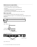
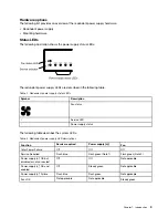
Page 10: ... if the RackSwitch internal power supply unit fails Major components This section describes the redundant power supply hardware components The G7000 redundant power supply is a 1U rack mountable DC power supply that supports up to four RackSwitches The following illustrations show the front panel and rear panel of the power supply Figure 1 G7000 Front view Figure 2 G7000 front panel detail Figure ...

Page 11: ... status Service LED Power supply status The following table describes the system LEDs Table 2 Redundant power supply LED descriptions Function Service required Power supply n Fan Total Power Failure Off Off Off Service Required Flash blue Flash green Note 1 Flash green Note 2 Power supply n OK but disabled or not connected Off Off Not applicable Power supply n OK and enabled Off Steady green Not a...

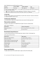
Page 12: ...racteristics The physical characteristics of the redundant power supply are listed in the following table Table 3 Physical characteristics Specification Physical characteristics Dimensions H x W x D 43 7 x 444 x 382 mm 1 72 x 17 3 x 15 0 in Weight 5 37 kg 11 84 lb Environmental specifications The environmental specifications for the redundant power supply are listed in the following table Table 4 ...

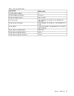
Page 13: ...rush current 102 4 A RMS 120 VAC 60 Hz 145 A RMS 230 VAC 50 Hz AC input current maximum 3 438 A RMS 120 VAC 60 Hz 1 760 A RMS 230 V 50 Hz Power delivery 78 W 12V DC output Four independent 12 V DC outputs ports per device Power supply rated output power 180 W each System power dissipation typical 245 VA System power dissipation maximum 413 VA Chapter 1 Introduction 5 ...

Page 14: ...6 Lenovo RackSwitch G7000 Redundant Power Supply Installation Guide ...

Page 15: ...te them Attention This product information is required to register your product place a service call and replace the unit After the redundant power supply is installed most of the labels are hidden from view and require removing the unit in order to relocate them Record this information below and print this page and keep it in a safe place for future reference You will need this information when y...

Page 16: ...s the basic environmental requirements for the redundant power supply Make sure the location where you install the redundant power supply meets the following requirements Install the redundant power supply in a dry clean well ventilated area Provide adequate space in the front and back of the redundant power supply to ensure proper air flow Make sure that an adequate grounded power supply is withi...

Page 17: ...ons systems networks and modems before you open the device covers unless instructed otherwise in the installation and configuration procedures Connect and disconnect cables as described in the following procedures when installing moving or opening covers on this product or attached devices To disconnect 1 Turn off everything unless instructed otherwise 2 Remove the power cords from the outlets 3 R...

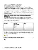
Page 18: ...ndoor humidity and increases static electricity Installing and removing the redundant power supply in a standard equipment rack This section describes how to install and remove the redundant power supply in a standard 19 inch equipment rack For information about mounting the redundant power supply in Lenovo System x racks see Installing and removing the redundant power supply in a Lenovo System x ...

Page 19: ...ore installing the redundant power supply Step 2 Remove the cover screws from the switch Step 3 Use the M4 screws to attach a mounting bracket to each side of the unit Torque the screws to approximately 1 13 newton meters Nm 10 inch pounds Step 4 Slide the redundant power supply into the rack Step 5 Use the M6 screws washers and clip nuts or cage nuts to secure the unit to the rack Torque the scre...

Page 20: ... Step 1 Disconnect all external cables Step 2 Loosen and remove M6 screws washers and clip nuts or cage nuts to remove the redundant power supply from the rack Step 3 Slide the redundant power supply out of the rack Step 4 Loosen and remove the M4 screws attaching the mounting bracket on each side of the redundant power supply 12 Lenovo RackSwitch G7000 Redundant Power Supply Installation Guide ...

Page 21: ...n a standard equipment rack The System x mounting kit must be purchased separately The following table lists the parts included in the System x 4 post mounting kit Table 7 System x rack mount kit parts Item number Description Quantity 1 Label 1 2 M6 locking washers 8 3 M3 screws 4 4 M6 screws 8 5 M6 clip nuts 8 6 M6 cage nuts 8 7 M4 screws 16 8 Filler plate 1 9 redundant power supply front bracket...

Page 22: ... redundant power supply 2 Remove the rear cover screws 3 Use the M4 screws to attach the front mounting brackets to each side of the redundant power supply Torque the screws to approximately 1 13 Nm 10 inch pounds 7 1 9 9 4 Use the M6 screws washers and clip nuts to connect the front mounting brackets to the front and rear posts in the rack Torque the screws to approximately 3 5 Nm 30 inch pounds ...

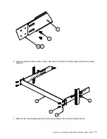
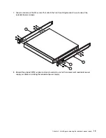
Page 23: ...e on the front mounting brackets 10 11 SEE STEP 5 6 Use M6 washers screws and clip nuts to attach the filler plate to the rear mounting brackets Torque the screws to approximately 3 5 Nm 30 inch pounds Chapter 2 Installing and removing the redundant power supply 15 ...

Page 24: ...Connect all external cables Removing the redundant power supply To remove the redundant power supply from a System x rack complete the following steps 1 Disconnect all external cables 2 Loosen and remove M3 screws that secure the rear brackets to the front brackets 16 Lenovo RackSwitch G7000 Redundant Power Supply Installation Guide ...

Page 25: ... and clip nuts that attach the filler plate to the rear mounting brackets 4 2 6 8 4 Slide the rear mounting brackets out of the slots available on the front mounting brackets Chapter 2 Installing and removing the redundant power supply 17 ...

Page 26: ...6 screws washers and clip nuts are used to connect the front mounting brackets to the front and rear posts in the rack 6 2 4 6 Slide the redundant power supply out of the rack 18 Lenovo RackSwitch G7000 Redundant Power Supply Installation Guide ...

Page 27: ...ckets to each side of the redundant power supply 7 1 9 9 8 Record the product MTM number and serial number to use for the replacement redundant power supply see Before installing the redundant power supply Chapter 2 Installing and removing the redundant power supply 19 ...

Page 28: ...20 Lenovo RackSwitch G7000 Redundant Power Supply Installation Guide ...

Page 29: ...equest that you upgrade your software and firmware if the problem has a documented solution within a software upgrade If you have installed new hardware or software in your environment check http www lenovo com us en serverproven to make sure that the hardware and software is supported by your product Go to https support lenovo com us en to check for information to help you solve the problem Gathe...

Page 30: ... The most current version of the product documentation is available in the following product specific Information Center System x products http systemx lenovofiles com help index jsp Software service and support Through IBM Support Line you can get telephone assistance for a fee with usage configuration and software problems with your Lenovo products For more information about Support Line and oth...

Page 31: ...publication Lenovo may make improvements and or changes in the product s and or the program s described in this publication at any time without notice The products described in this document are not intended for use in implantation or other life support applications where malfunction may result in injury or death to persons The information contained in this document does not affect or change Lenov...

Page 32: ...drives and population of all hard disk drive bays with the largest currently supported drives that are available from Lenovo Maximum memory might require replacement of the standard memory with an optional memory module Each solid state memory cell has an intrinsic finite number of write cycles that the cell can incur Therefore a solid state device has a maximum number of write cycles that it can ...

Page 33: ...4 19853 Silver Corrosion rate of less than 300 Å in 30 days 1 ASHRAE 52 2 2008 Method of Testing General Ventilation Air Cleaning Devices for Removal Efficiency by Particle Size Atlanta American Society of Heating Refrigerating and Air Conditioning Engineers Inc 2 The deliquescent relative humidity of particulate contamination is the relative humidity at which the dust absorbs enough water to beco...

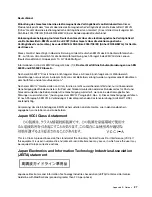
Page 34: ...ept responsibility for any failure to satisfy the protection requirements resulting from a non recommended modification of the product including the installation of option cards from other manufacturers This product has been tested and found to comply with the limits for Class A equipment according to European Standards harmonized in the Directives in compliance The limits for Class A equipment we...

Page 35: ...Wohnbereich Funkstörungen verursachen in diesem Fall kann vom Betreiber verlangt werden angemessene Maßnahmen durchzuführen und dafür aufzukommen Nach dem EMVG Geräte dürfen an Orten für die sie nicht ausreichend entstört sind nur mit besonderer Genehmigung des Bundesministers für Post und Telekommunikation oder des Bundesamtes für Post und Telekommunikation betrieben werden Die Genehmigung wird e...

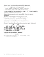
Page 36: ...pe A Sellers and users need to pay attention to it This is for any areas other than home Russia Electromagnetic Interference EMI Class A statement People s Republic of China Class A electronic emission statement Taiwan Class A compliance statement 28 Lenovo RackSwitch G7000 Redundant Power Supply Installation Guide ...

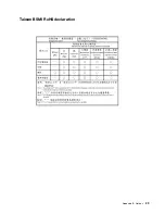
Page 37: ...Taiwan BSMI RoHS declaration Appendix B Notices 29 ...

Page 38: ...30 Lenovo RackSwitch G7000 Redundant Power Supply Installation Guide ...

Page 39: ...rements 1 help from the World Wide Web 22 from World Wide Web 22 help sources of 21 I important notes 24 important notices 1 information center 22 installation requirements 2 installing before information 7 installing the RPS unit standard rack 11 System x rack 14 introduction 1 J Japan Electronics and Information Technology Industries Association statement 27 JEITA statement 27 K Korea Class A el...

Page 40: ...hysical 4 power 4 standard rack installing the redundant power supply 11 removing the redundant power supply 12 statements and notices 1 System x rack installing the redundant power supply 14 removing the redundant power supply 16 T Taiwan BSMI RoHS declaration 29 Taiwan Class A electronic emission statement 28 Taiwan product service 22 telecommunication regulatory statement 25 telephone numbers 2...

Page 41: ......

Page 42: ......
Reviews: