


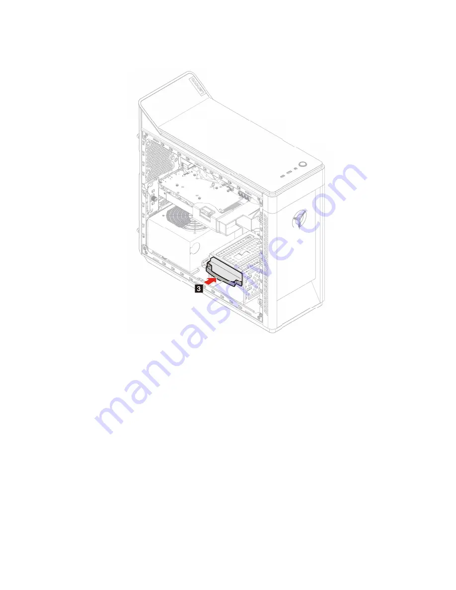
9. Insert the storage drive tray into the storage drive bay.
10. Reinstall all removed parts. Then, reconnect the power cord and all disconnected cables to the
computer.
2.5-inch storage drive
Prerequisite
Before you start, read Appendix A “Important safety information” on page 73 and print the following
instructions.
Attention:
The internal storage drive is sensitive. Inappropriate handling might cause damage and
permanent loss of data. When handling the internal storage drive, observe the following guidelines:
• Replace the internal storage drive only for upgrade or repair. The internal storage drive is not designed for
frequent changes or replacement.
• Before replacing the internal storage drive, make a backup copy of all the data that you want to keep.
• Do not touch the contact edge of the internal storage drive. Otherwise, the internal storage drive might get
damaged.
• Do not apply pressure to the internal storage drive.
• Do not make the internal storage drive subject to physical shocks or vibration. Put the internal storage
drive on a soft material, such as cloth, to absorb physical shocks.
38
User Guide
Summary of Contents for 90NC007PUS
Page 1: ...User Guide Lenovo Legion Tower 5 28L 05 and Lenovo Legion R5 28L 05 ...
Page 4: ...ii User Guide ...
Page 6: ...iv User Guide ...
Page 8: ...Figure 2 Lenovo Legion R5 28L 05 1 Lenovo Legion logo LED indicator 2 User Guide ...
Page 9: ...Top Figure 3 Lenovo Legion Tower 5 28L 05 Chapter 1 Meet your computer 3 ...
Page 14: ...8 User Guide ...
Page 30: ...24 User Guide ...
Page 34: ...5 Remove the left side cover 6 Install the new left side cover 28 User Guide ...
Page 38: ...4 Open the tabs and remove the front bezel 32 User Guide ...
Page 40: ...5 Open the tabs and remove the back cover 34 User Guide ...
Page 52: ...3 Disengage the tabs on the memory modules 4 Remove the memory module 46 User Guide ...
Page 56: ...6 Install the new heatsink and fan 7 Screw in the heatsink mounting screws 50 User Guide ...
Page 57: ...8 Plug the fan power cable into the motherboard Chapter 5 CRU replacement 51 ...
Page 62: ...5 Open the latch 6 Remove the PCI Express card super holder screws 56 User Guide ...
Page 72: ...7 Remove the power supply assembly 8 Install the new power supply assembly 66 User Guide ...
Page 78: ...72 User Guide ...
Page 92: ...86 User Guide ...
Page 108: ...102 User Guide ...
Page 111: ......
Page 112: ......


