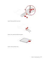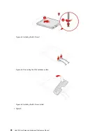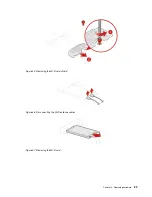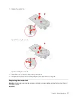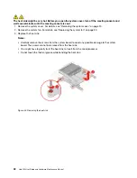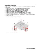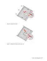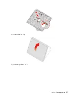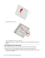
Figure 58. Installing the screws and the standoff
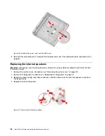
9. Route and connect all the cables to the new system board.
10. Reinstall the removed parts. To complete the replacement, see “Completing the parts replacement” on
Replacing a memory module
Attention:
Do not open your meeting console or attempt any repairs before reading the
Important Product
Information Guide
.
1. Remove the system cover. For details, see “Removing the system cover” on page 20.
2. Remove the system fan. For details, see “Replacing the system fan” on page 30.
3. Remove the heat sink. For details, see “Replacing the heat sink” on page 31.
4. Remove the system board. For details, see “Replacing the system board” on page 39.
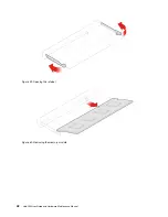
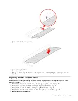
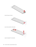
5. Replace the memory module.
.
41
Summary of Contents for 10V5
Page 1: ...Hub 500 User Guide and Hardware Maintenance Manual Machine Types 10V5 and 10V6 ...
Page 4: ...ii Hub 500 User Guide and Hardware Maintenance Manual ...
Page 12: ...8 Hub 500 User Guide and Hardware Maintenance Manual ...
Page 14: ...10 Hub 500 User Guide and Hardware Maintenance Manual ...
Page 16: ...12 Hub 500 User Guide and Hardware Maintenance Manual ...
Page 64: ...60 Hub 500 User Guide and Hardware Maintenance Manual ...
Page 66: ...62 Hub 500 User Guide and Hardware Maintenance Manual ...
Page 67: ......
Page 68: ......

