


Page 24 - IOM / ROOF-TOP FLEXY™ Series
AIRFLOW BALANCING
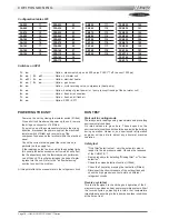
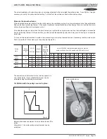
2nd method when adjusting the pulley :
- Close the pulley fully and count the number of turns
from fully closed position. Using table 1 determine the
motor pulley actual diameter.
- Record the fix fan pulley diameter.(DF)
- Determine the fan speed using the following formula:
rpm FAN = rpm MOTOR x DM / DF
Where :
rpm MOTOR : ....... from the motor plate or table 2
DM : ...................... from table 1
DF: ........................ from machine
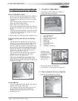
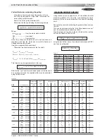
Once the pulleys are adjusted and the belt checked and
tensioned, start the fan motor and record the Amps and
Voltage between the phases :
Using the measured data and table 2
- Theoretical mechanical power at the fan shaft :
P
meca fan
= P
meca Motor
x
η
Transmission
P
meca fan
= P
elec
x
η
meca motor
x
η
Transmission
P
meca fan
= V x I x
√
3 x cos
ϕ
x
η
meca motor
x
η
Transmission
This formula can be approximated in this way
P
meca fan
= V x I x 1.73 x 0.85 x 0.76 x 0.9
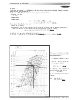
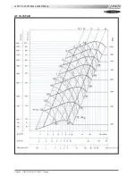
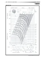
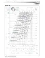
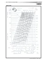
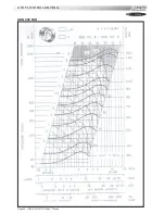
With the fan "rpm" and the mechanical power at the fan shaft
an operating point and the supplied airflow can be estimated
using the fan curves.
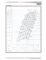
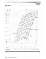
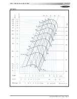
CHECKING AIRFLOW AND ESP
Using the fan curves on page 25, 26, 27, the airflow, the total
pressure available (P
TOT
) and the corresponding dynamic
pressure (Pd) can now be estimated, for a specific operating
point;
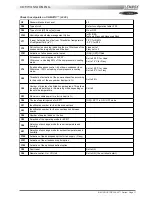
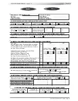
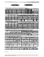
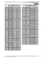
The next step consist in estimating the pressure losses across
the unit.
This can be achieved using the "dirty filter pressure sensor"
and the accessories pressure drop table:
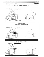
Also the pressure drop due to the duct inlet into the roof-top
unit can be taken as 20 to 30 Pa.
∆
P
INT
=
∆
P
filter
+ coil + P
Inlet
+
∆
P
Options
using the results from above, the external static pressure (ESP)
can then be estimated:
ESP = P
TOT
- Pd -
∆
P
INT
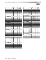
Table 2
Motor Size
Nom, Speed
Cos
meca motor
0,75 kW
1400 rpm
0,77
0,70
1,1 kW
1425 rpm
0,82
0,77
1,5 kW
1430 rpm
0,81
0,75
2,2 kW
1430 rpm
0,81
0,76
3,0 kW
1425 rpm
0,78
0,77
4 kW
1425 rpm
0,79
0,80
5,5 kW
1430 rpm
0,82
0,82
Economiser
EU7
Hot water coil
Electric heater
Roofcurb
Horizontal
Gaz
100% open
Filter
S
H
S
H
Base frame
Roofcurb
H
SIZE
Air flow (m
3
/h)
(Pa)
(Pa)
(Pa)
(Pa)
(Pa)
(Pa)
(Pa)
(Pa)
(Pa)
Min.
10 000
4
67
12
14
5
8
10
41
22
60
Nom.
12 000
6
93
16
19
8
8
11
59
26
Max.
15 000
9
135
24
28
8
10
13
92
31
Min.
12 000
6
56
6
12
5
5
13
59
29
70
Nom.
14 000
8
73
8
16
5
5
16
80
34
Max.
18 000
12
113
13
25
8
8
22
132
47
Min.
14 000
8
73
8
16
5
8
18
44
7
85
Nom.
16 000
10
113
13
25
8
8
26
57
10
Max.
22 000
16
159
18
36
8
10
32
109
12
Min.
16 000
10
93
10
20
8
10
26
57
10
100
Nom.
20 000
14
135
15
30
10
13
32
90
12
Max.
22 000
16
159
18
36
13
15
38
109
15
Min.
18 000
12
113
13
25
10
13
32
33
29
120
Nom.
22 000
16
159
18
36
13
15
38
49
35
Max.
24 000
18
184
21
41
15
18
44
58
40
Min.
20 000
14
135
15
30
10
15
35
40
31
140
Nom.
24 000
18
184
21
41
15
18
46
58
40
Max.
25 000
19
197
22
44
15
20
50
63
43
Min.
22 000
16
87
9
18
8
8
24
49
45
160
Nom.
28 000
22
132
13
27
8
10
30
79
56
Max.
32 000
26
165
17
34
13
13
34
103
64
Min.
24 000
18
101
10
20
10
10
34
58
64
190
Nom.
33 000
27
174
18
36
13
13
41
109
77
Max.
36 000
30
201
21
41
13
15
48
130
89
Table 5.52
Summary of Contents for ROOFTOP FLEXY FCA 100
Page 1: ...INSTALLATION OPERATING MAINTENANCE MANUAL ROOFTOP FLEXY English August 2003 ...
Page 2: ......
Page 33: ...IOM ROOF TOP FLEXY Series Page 31 AIR FLOW BALANCING AT 12 12 FAN ...
Page 34: ...Page 32 IOM ROOF TOP FLEXY Series AIR FLOW BALANCING AT 15 15 FAN ...
Page 35: ...IOM ROOF TOP FLEXY Series Page 33 AIR FLOW BALANCING AT 18 13 ...
Page 36: ...Page 34 IOM ROOF TOP FLEXY Series AIR FLOW BALANCING AT 18 18 FAN ...
Page 37: ...IOM ROOF TOP FLEXY Series Page 35 AIR FLOW BALANCING RDN 450 FAN ...
Page 38: ...Page 36 IOM ROOF TOP FLEXY Series AIR FLOW BALANCING ADN 355 FAN ...
Page 39: ...IOM ROOF TOP FLEXY Series Page 37 AIR FLOW BALANCING ADN 400 FAN ...
Page 40: ...Page 38 IOM ROOF TOP FLEXY Series AIR FLOW BALANCING ADN 450 FAN ...
Page 104: ...Page 102 IOM ROOF TOP FLEXY Series ELECTRICAL WIRING DIAGRAMS MAIN CURRENT DIAGRAM ...
Page 106: ...Page 104 IOM ROOF TOP FLEXY Series ELECTRICAL WIRING DIAGRAMS CLIMATIC CONTROLLER ...
Page 108: ...Page 106 IOM ROOF TOP FLEXY Series ELECTRICAL WIRING DIAGRAMS CLIMATIC INPUT FG FD ...
Page 112: ...Page 110 IOM ROOF TOP FLEXY Series ELECTRICAL WIRING DIAGRAMS GAS BURNER 180 Kw ...
Page 132: ...Page 130 IOM ROOF TOP FLEXY Series ISO 9001 CERTIFICATION ...
Page 133: ...IOM ROOF TOP FLEXY Series Page 131 PED CERTIFICATION OF CONFORMITY ...
Page 134: ...Page 132 IOM ROOF TOP FLEXY Series GLASS WOOL FIRE CLASS ...
Page 135: ...IOM ROOF TOP FLEXY Series Page 133 33 kW GAS BURNER CE CERTIFICATION OF CONFORMITY ...
Page 136: ...Page 134 IOM ROOF TOP FLEXY Series 60 kW GAS BURNER CE CERTIFICATION OF CONFORMITY ...
Page 137: ...IOM ROOF TOP FLEXY Series Page 135 120 kW GAS BURNER CE CERTIFICATION OF CONFORMITY ...
Page 138: ...Page 136 IOM ROOF TOP FLEXY Series 180 kW GAS BURNER CE CERTIFICATION OF CONFORMITY ...
Page 139: ...IOM ROOF TOP FLEXY Series Page 137 INSULATION FIRE CLASS ...
Page 140: ...Page 138 IOM ROOF TOP FLEXY Series INSULATION FIRE CLASS ...
Page 141: ......


