IOM / ROOF-TOP FLEXY™ Series - Page 125
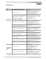
maintenance diagnostic
FAULT
Heat Pump mode
: Circuit breaker
open
POSSIBLE CAUSE AND SYMPTOMS
High Amps due to a low voltage from the main
supply
High amps due to freezing of the coil
Flexy : Water ingress in the motor connection
box.
SOLUTION
Check the voltage drop when all components
are running.
Change the circuit breaker for one with a higher
rating.
Check the adjustable amps on the motor
starter.
Adjust the defrost cycle set points.
Change the component
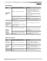
OUTDOOR AXIAL FAN
FAULT
High Temperature
trip out on
electric heater
POSSIBLE CAUSE AND SYMPTOMS
Low airflow rate
Incorrect position of the Klixon
SOLUTION
Measure and estimate the airflow and pressure
and compare with the specification from
customer.
Check that the Klixon, is positioned in the
airflow, relocate Klixon if necessary
Check that there is no heat transfer from the
Klixon support.
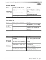
ELECTRIC HEATER
FAULT
Water found in
the ventilation
section
Water ingress in
the filter
compartment
POSSIBLE CAUSE AND SYMPTOMS
Cooling mode:
Water carried away from the coil because of
excessive airflow and speed on the coil.
Low air pressure in the compartment due to a
high airflow rate or a high pressure drop before
the fan
Check seals around the ventilation section.
Water ingress through a leaking fresh air hood
or when running 100% fresh air
SOLUTION
Estimate the airflow rate and check the speed
is lower than 2.8 m/s
Check filter
Reduce airflow rate
Check the door seal
Check for the presence of silicone seals in the
corners of the door and at the bottom of the
refrigeration section bulkhead.
Check the seals and flanges in the fresh air
hood
Reduce the airflow rate if necessary
ELECTRIC HEATER
Summary of Contents for ROOFTOP FLEXY FCA 100
Page 1: ...INSTALLATION OPERATING MAINTENANCE MANUAL ROOFTOP FLEXY English August 2003 ...
Page 2: ......
Page 33: ...IOM ROOF TOP FLEXY Series Page 31 AIR FLOW BALANCING AT 12 12 FAN ...
Page 34: ...Page 32 IOM ROOF TOP FLEXY Series AIR FLOW BALANCING AT 15 15 FAN ...
Page 35: ...IOM ROOF TOP FLEXY Series Page 33 AIR FLOW BALANCING AT 18 13 ...
Page 36: ...Page 34 IOM ROOF TOP FLEXY Series AIR FLOW BALANCING AT 18 18 FAN ...
Page 37: ...IOM ROOF TOP FLEXY Series Page 35 AIR FLOW BALANCING RDN 450 FAN ...
Page 38: ...Page 36 IOM ROOF TOP FLEXY Series AIR FLOW BALANCING ADN 355 FAN ...
Page 39: ...IOM ROOF TOP FLEXY Series Page 37 AIR FLOW BALANCING ADN 400 FAN ...
Page 40: ...Page 38 IOM ROOF TOP FLEXY Series AIR FLOW BALANCING ADN 450 FAN ...
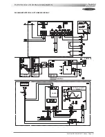
Page 104: ...Page 102 IOM ROOF TOP FLEXY Series ELECTRICAL WIRING DIAGRAMS MAIN CURRENT DIAGRAM ...
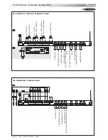
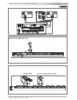
Page 106: ...Page 104 IOM ROOF TOP FLEXY Series ELECTRICAL WIRING DIAGRAMS CLIMATIC CONTROLLER ...
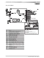
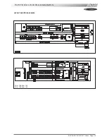
Page 108: ...Page 106 IOM ROOF TOP FLEXY Series ELECTRICAL WIRING DIAGRAMS CLIMATIC INPUT FG FD ...
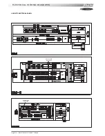
Page 112: ...Page 110 IOM ROOF TOP FLEXY Series ELECTRICAL WIRING DIAGRAMS GAS BURNER 180 Kw ...
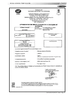
Page 132: ...Page 130 IOM ROOF TOP FLEXY Series ISO 9001 CERTIFICATION ...
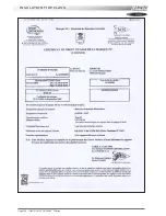
Page 133: ...IOM ROOF TOP FLEXY Series Page 131 PED CERTIFICATION OF CONFORMITY ...
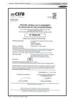
Page 134: ...Page 132 IOM ROOF TOP FLEXY Series GLASS WOOL FIRE CLASS ...
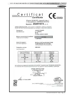
Page 135: ...IOM ROOF TOP FLEXY Series Page 133 33 kW GAS BURNER CE CERTIFICATION OF CONFORMITY ...
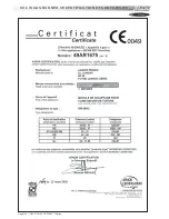
Page 136: ...Page 134 IOM ROOF TOP FLEXY Series 60 kW GAS BURNER CE CERTIFICATION OF CONFORMITY ...
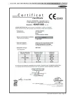
Page 137: ...IOM ROOF TOP FLEXY Series Page 135 120 kW GAS BURNER CE CERTIFICATION OF CONFORMITY ...
Page 138: ...Page 136 IOM ROOF TOP FLEXY Series 180 kW GAS BURNER CE CERTIFICATION OF CONFORMITY ...
Page 139: ...IOM ROOF TOP FLEXY Series Page 137 INSULATION FIRE CLASS ...
Page 140: ...Page 138 IOM ROOF TOP FLEXY Series INSULATION FIRE CLASS ...
Page 141: ......

