


IOM / ROOF-TOP FLEXY™ Series - Page 73
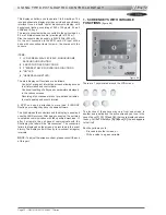
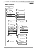
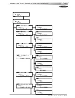
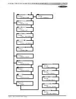
USING THE KP07 GRAPHIC CONTROL DISPLAY
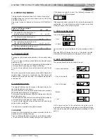
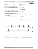
2 - FIXED KEYS (FIGURE 69)
The functions of these 5 keys are fixed :
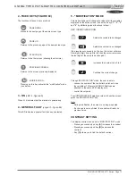
PAGE DOWN :
Moves to the next page of the same screen type.
PAGE UP :
Returns to the previous page of the same screen type.
STRUCTURE :
Returns to the first screen (showing the structure).
PREVIOUS SCREEN :
Returns to the screen previously displayed
MODIFICATION :
Pressing on this key activates the "modification" mode
(see below).
3 - ON
(LED 4 - figure 69)
When lit, it indicates that the machine is powered up.
4 - GENERAL FAULT
(voyant 5 - figure 69)
This LED indicates a general fault has been detected.
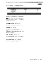
5 - "MODIFICATION" MODE
This mode allows you to change the values of all the variables
displayed on the active screen. It uses the 4 keys "
1
", "
2
", "
3
"
and "
4
" by attributing preset functions to them :
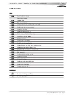
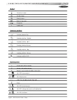
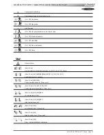
KEY / ASSOCIATED ICON
Selects the variable to be changed
Selects the number to be changed
(By pressing successively on the key the cursor will move
from digit to digit, from right to left, then the cursor remains on
the last digit of the value to be changed.)
Increases the number from 0 to 9
Confirms the current change.
Through "MODIFICATION" mode, the user is able to :
- choose the number of the controller he wishes to see
the variables of (if several LENNOX Rooftops are
attached to the same KP07 display unit),
- control the setpoints.
To exit "MODIFICATION" mode and return to the active screen,
press the "MODIFICATION" key.
Note :
- During modification, the screen is no longer updated.
- If a change is not confirmed, the variable will retain its
previous value.
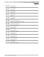
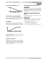
CONTRAST SETTING
The display contrast can be set in "MODIFICATION" mode :
- Pressing successively on key
[A]
increases the contrast.
- Pressing successively on key
[B]
decreases the
contrast.
- Key
[C]
allows you to find the default contrast.
Summary of Contents for ROOFTOP FLEXY FCA 100
Page 1: ...INSTALLATION OPERATING MAINTENANCE MANUAL ROOFTOP FLEXY English August 2003 ...
Page 2: ......
Page 33: ...IOM ROOF TOP FLEXY Series Page 31 AIR FLOW BALANCING AT 12 12 FAN ...
Page 34: ...Page 32 IOM ROOF TOP FLEXY Series AIR FLOW BALANCING AT 15 15 FAN ...
Page 35: ...IOM ROOF TOP FLEXY Series Page 33 AIR FLOW BALANCING AT 18 13 ...
Page 36: ...Page 34 IOM ROOF TOP FLEXY Series AIR FLOW BALANCING AT 18 18 FAN ...
Page 37: ...IOM ROOF TOP FLEXY Series Page 35 AIR FLOW BALANCING RDN 450 FAN ...
Page 38: ...Page 36 IOM ROOF TOP FLEXY Series AIR FLOW BALANCING ADN 355 FAN ...
Page 39: ...IOM ROOF TOP FLEXY Series Page 37 AIR FLOW BALANCING ADN 400 FAN ...
Page 40: ...Page 38 IOM ROOF TOP FLEXY Series AIR FLOW BALANCING ADN 450 FAN ...
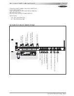
Page 104: ...Page 102 IOM ROOF TOP FLEXY Series ELECTRICAL WIRING DIAGRAMS MAIN CURRENT DIAGRAM ...
Page 106: ...Page 104 IOM ROOF TOP FLEXY Series ELECTRICAL WIRING DIAGRAMS CLIMATIC CONTROLLER ...
Page 108: ...Page 106 IOM ROOF TOP FLEXY Series ELECTRICAL WIRING DIAGRAMS CLIMATIC INPUT FG FD ...
Page 112: ...Page 110 IOM ROOF TOP FLEXY Series ELECTRICAL WIRING DIAGRAMS GAS BURNER 180 Kw ...
Page 132: ...Page 130 IOM ROOF TOP FLEXY Series ISO 9001 CERTIFICATION ...
Page 133: ...IOM ROOF TOP FLEXY Series Page 131 PED CERTIFICATION OF CONFORMITY ...
Page 134: ...Page 132 IOM ROOF TOP FLEXY Series GLASS WOOL FIRE CLASS ...
Page 135: ...IOM ROOF TOP FLEXY Series Page 133 33 kW GAS BURNER CE CERTIFICATION OF CONFORMITY ...
Page 136: ...Page 134 IOM ROOF TOP FLEXY Series 60 kW GAS BURNER CE CERTIFICATION OF CONFORMITY ...
Page 137: ...IOM ROOF TOP FLEXY Series Page 135 120 kW GAS BURNER CE CERTIFICATION OF CONFORMITY ...
Page 138: ...Page 136 IOM ROOF TOP FLEXY Series 180 kW GAS BURNER CE CERTIFICATION OF CONFORMITY ...
Page 139: ...IOM ROOF TOP FLEXY Series Page 137 INSULATION FIRE CLASS ...
Page 140: ...Page 138 IOM ROOF TOP FLEXY Series INSULATION FIRE CLASS ...
Page 141: ......


