IOM / ROOF-TOP FLEXY™ Series - Page 87
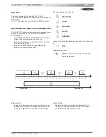
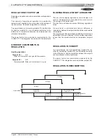
REGULATION IN HUMIDIFYING
100%
0%
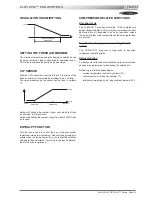
SETTING THE FRESH AIR MINIMUM
The minimum value for opening the damper to outside air can
be set by instruction (see configuration of operating zones).
This value is expressed directly as a percentage.
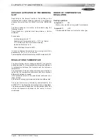
CO² SENSOR
Where a CO² sensor is connected to the unit, the value of the
fresh air minimum is calculated according to the CO² ratio.
The value measured by the sensor can be read in variable
17.
2000 ppm
CO2
0 ppm
100%
Setpoint 47 defines the number of ppm up to which the fresh
air minimum is still achieved.
Setpoint 48 defines the number of ppm from which 100% fresh
air is used.
ENTHALPY FUNCTION
This function is used to control the use of the economiser
register according to air enthalpy. If the outside hygrometry is
greater than the inside hygrometry, the respective enthalpy
values are then calculated. According to the result obtained,
input of new air is optimised.
CLIMATIC™ PARAMETERS
COMPRESSOR-RELATED FUNCTIONS
Anti-short cycle
The CLIMATIC™ provides protection of the compressors
against frequent restarts. This is why the compressors cannot
be started, even if requested to do so by regulation, unless
the time since they were last put into operation is greater than
six minutes.
Equalisation of compressor operating times (F
series)
The CLIMATIC™ program is organised to equalise
compressor operating times
Defrost function
For heat pump units and air condensation units, cycle inversion
phases are programmed for defrosting the outside coil.
Defrosting is activated depending on :
- outside temperature (limit set by setpoint 76),
- coil temperature (limit set by setpoint 77),
- with overall weighting by an icing constant (setpoint 78).
Humidity band %
setpoint 65
Setpoint 47
Setpoint 48
Summary of Contents for ROOFTOP FLEXY FCA 100
Page 1: ...INSTALLATION OPERATING MAINTENANCE MANUAL ROOFTOP FLEXY English August 2003 ...
Page 2: ......
Page 33: ...IOM ROOF TOP FLEXY Series Page 31 AIR FLOW BALANCING AT 12 12 FAN ...
Page 34: ...Page 32 IOM ROOF TOP FLEXY Series AIR FLOW BALANCING AT 15 15 FAN ...
Page 35: ...IOM ROOF TOP FLEXY Series Page 33 AIR FLOW BALANCING AT 18 13 ...
Page 36: ...Page 34 IOM ROOF TOP FLEXY Series AIR FLOW BALANCING AT 18 18 FAN ...
Page 37: ...IOM ROOF TOP FLEXY Series Page 35 AIR FLOW BALANCING RDN 450 FAN ...
Page 38: ...Page 36 IOM ROOF TOP FLEXY Series AIR FLOW BALANCING ADN 355 FAN ...
Page 39: ...IOM ROOF TOP FLEXY Series Page 37 AIR FLOW BALANCING ADN 400 FAN ...
Page 40: ...Page 38 IOM ROOF TOP FLEXY Series AIR FLOW BALANCING ADN 450 FAN ...
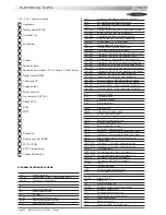
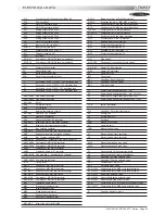
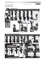
Page 104: ...Page 102 IOM ROOF TOP FLEXY Series ELECTRICAL WIRING DIAGRAMS MAIN CURRENT DIAGRAM ...
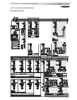
Page 106: ...Page 104 IOM ROOF TOP FLEXY Series ELECTRICAL WIRING DIAGRAMS CLIMATIC CONTROLLER ...
Page 108: ...Page 106 IOM ROOF TOP FLEXY Series ELECTRICAL WIRING DIAGRAMS CLIMATIC INPUT FG FD ...
Page 112: ...Page 110 IOM ROOF TOP FLEXY Series ELECTRICAL WIRING DIAGRAMS GAS BURNER 180 Kw ...
Page 132: ...Page 130 IOM ROOF TOP FLEXY Series ISO 9001 CERTIFICATION ...
Page 133: ...IOM ROOF TOP FLEXY Series Page 131 PED CERTIFICATION OF CONFORMITY ...
Page 134: ...Page 132 IOM ROOF TOP FLEXY Series GLASS WOOL FIRE CLASS ...
Page 135: ...IOM ROOF TOP FLEXY Series Page 133 33 kW GAS BURNER CE CERTIFICATION OF CONFORMITY ...
Page 136: ...Page 134 IOM ROOF TOP FLEXY Series 60 kW GAS BURNER CE CERTIFICATION OF CONFORMITY ...
Page 137: ...IOM ROOF TOP FLEXY Series Page 135 120 kW GAS BURNER CE CERTIFICATION OF CONFORMITY ...
Page 138: ...Page 136 IOM ROOF TOP FLEXY Series 180 kW GAS BURNER CE CERTIFICATION OF CONFORMITY ...
Page 139: ...IOM ROOF TOP FLEXY Series Page 137 INSULATION FIRE CLASS ...
Page 140: ...Page 138 IOM ROOF TOP FLEXY Series INSULATION FIRE CLASS ...
Page 141: ......

