Page 49
VI-MAINTENANCE
WARNING
ELECTRICAL SHOCK, FIRE,
OR EXPLOSION HAZARD.
Failure to follow safety warnings exactly could
result in dangerous operation, serious injury, death
or property damage.
Improper servicing could result in dangerous
operation, serious injury, death, or property damage.
Before servicing, disconnect all electrical power to
the furnace.
At the beginning of each heating season, system should
be checked as follows by a qualified service technician:
Blower
Check the blower wheel for debris and clean if necessary.
The blower motors are prelubricated for extended bearing
life. No further lubrication is needed.
WARNING
The blower access panel must be securely in place
when the blower and burners are operating. Gas
fumes, which could contain carbon monoxide, can
be drawn into living space resulting in personal
injury or death.
Filters
All air filters are installed external to the unit. Filters should
be inspected monthly. Clean or replace the filters when
necessary to ensure proper furnace operation. TABLE 22
lists recommended filter sizes.
WARNING
If a highefficiency filter is being installed as part
of this system to ensure better indoor air quality,
the filter must be properly sized. Highefficiency
filters have a higher static pressure drop than
standardefficiency glass/foam filters.
If the pressure drop is too great, system capacity
and performance may be reduced. The pressure
drop may also cause the limit to trip more frequently
during the winter and the indoor coil to freeze in the
summer, resulting in an increase in the number of
service calls.
Before using any filter with this system, check the
specifications provided by the filter manufacturer against
the data given in the appropriate Lennox Product
Specifications bulletin. Additional information is provided
in Service and Application Note ACC002
(August 2000).
TABLE 22
Furnace
Cabinet Width
Filter Size
Side Return
Bottom Return
17-1/2”
16 X 25 X 1 (1)
16 X 25 X 1 (1)
21”
16 X 25 X 1 (1)
20 X 25 X 1 (1)
24-1/2”
16 X 25 X 1 (2)
24 X 25 X (1)
Check the exhaust and air intake pipes and all connec
-
tions for tightness and to make sure there is no blockage.
NOTE -
After any heavy snow, ice or frozen fog event the
furnace vent pipes may become restricted. Always check
the vent system and remove any snow or ice that may be
obstructing the plastic intake or exhaust pipes.
Electrical
WARNING
Fire Hazard. Use of aluminum wire with this product
may result in a fire, causing property damage,
severe injury or death. Use copper wire only with
this product.
WARNING
Failure to use properly sized wiring and circuit
breaker may result in property damage. Size wiring
and circuit breaker(s) per Product Specifications
bulletin (EHB) and unit rating plate.
1 -
Check all wiring for loose connections.
2 - Check for the correct voltage at the furnace (furnace
operating). Correct voltage is 10%
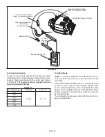
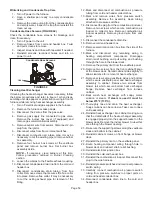
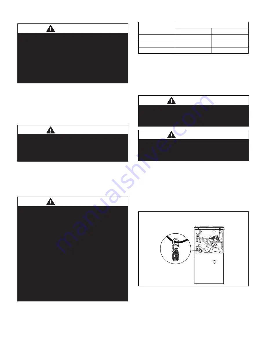
3 - Check amp-draw using a true RMS meter on the
blower motor with blower access panel in place.
See FIGURE 61.
Furnace Nameplate__________Actual__________
Check Motor AMP Draw
(Typical set−up with upflow furnace shown)
kVAr
kWh
COM
M
V3
V1 V2
POFF
MR
EX
1
W
3
2
True RMS Meter
FIGURE 61
Summary of Contents for ML196UH030XE36B
Page 57: ...Page 57...

