Page 38
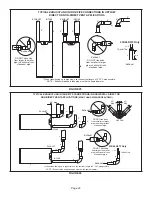
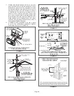
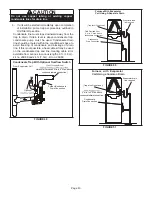
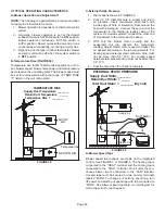
Details of Exhaust Piping Terminations for Non-Direct
Vent Applications
Exhaust pipes may be routed either horizontally through
an outside wall or vertically through the roof. In attic or
closet installations, vertical termination through the roof
is preferred. FIGURE 43 and FIGURE 44 shows typical
terminations.
1 -
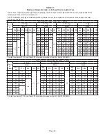
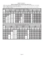
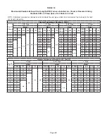
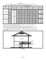
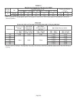
Exhaust piping must terminate straight out or up
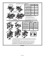
as shown. The termination pipe must be sized as
listed in TABLE 16. The specified pipe size ensures
proper velocity required to move the exhaust gases
away from the building.
2 - On field supplied terminations for side wall exit,
exhaust piping may extend a maximum of 12 inches
(305mm) for 2” PVC and 20 inches (508mm) for 3”
(76mm) PVC beyond the outside wall.
3 - If exhaust piping must be run up a side wall
to position above snow accumulation or other
obstructions, piping must be supported every 24
inches (610mm). When exhaust piping must be run
up an outside wall, any reduction in exhaust pipe
size must be done after the final elbow.
4 - Distance between exhaust pipe terminations on
multiple furnaces must meet local codes
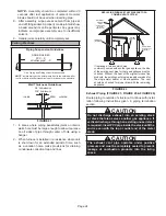
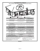
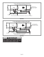
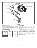
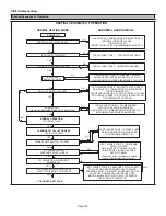
NON-DIRECT VENT ROOF TERMINATION KIT
(15F75 or 44J41)
UNCONDITIONED
ATTIC SPACE
3” (76mm) OR
2” (51mm) PVC
PROVIDE SUPPORT
FOR EXHAUST LINES
12” (305mm)
ABOVE AVE.
SNOW
ACCUMULATION
FIGURE 43
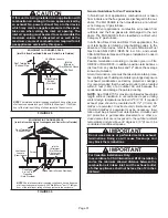
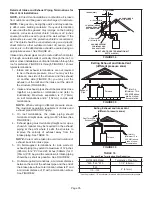
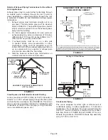
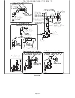
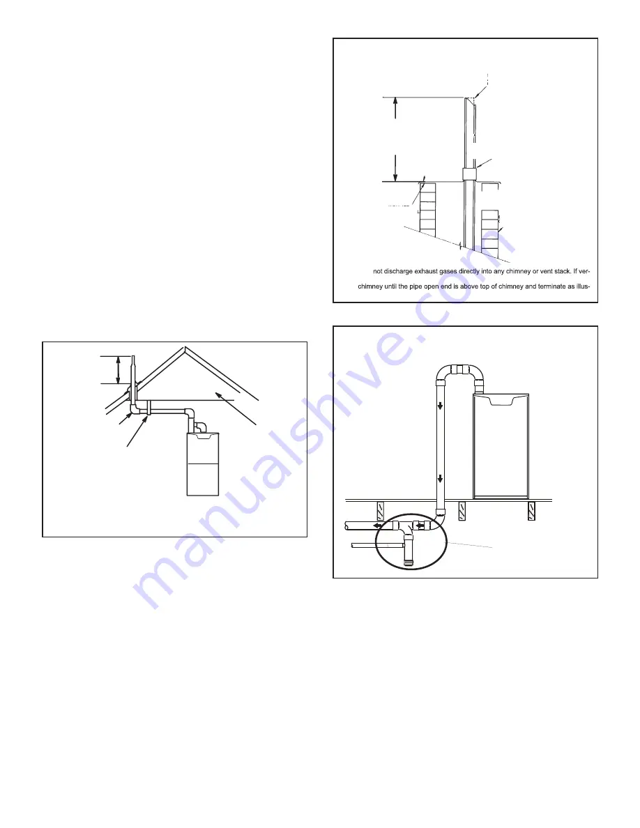
Crawl Space and Extended Horizontal Venting
Lennox provides kit 51W18 (USA) kit 15Z70 (Canada) to
install 2” or 3” PVC exhaust piping through the floor joists
and into the the crawl space. See FIGURE 45. This kit can
also be used as a supplemental drain for installations with
condensate run back in the vent pipe (ie. long horizontal
runs, unconditioned spaces, etc.).
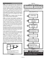
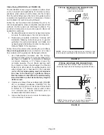
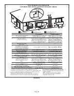
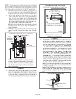
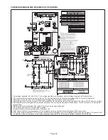
NOTE - Do
tical discharge through an existing unused chimney or stack is required, insert piping
inside
trated. In any exterior portion of chimney, the exhaust vent must be insulated.
STRAIGHT-CUT OR
ANGLE-CUT IN DIRECTION
OF ROOF SLOPE
SHOULDER OF FITTINGS
PROVIDE SUPPORT
OF PIPE ON TOP PLATE
EXTERIOR
PORTION OF
CHIMNEY
INSULATE
TO FORM
SEAL
SHEET
METAL TOP
PLATE
NON-DIRECT VENT APPLICATION
USING EXISTING CHIMNEY
Minimum 12” (305MM)
above chimney top
plate or average snow
accumulation
FIGURE 44
Venting In A Crawl Space
Basement Floor
KIT 51W18
(USA)
KIT 15Z70
(CANADA)
FIGURE 45
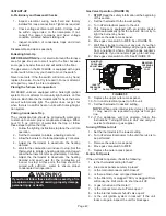
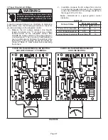
Condensate Piping
This unit is designed for either right- or left-side exit of
condensate piping in upflow applications. In horizontal
applications, the condensate trap must extend below the
unit. An 8” service clearance is required for the conden
-
sate trap. Refer to FIGURE 46 and FIGURE 47 for con
-
densate trap locations. FIGURE 54 shows trap assembly
using 1/2” PVC or 3/4” PVC.
Summary of Contents for ML196UH030XE36B
Page 57: ...Page 57...


