Page 13
Defrost Control Timing Pins
Each timing pin selection provides a different accumu-
lated compressor run time period during one thermo-
stat run cycle. This time period must occur before a de-
frost cycle is initiated. The defrost interval can be ad-
justed to 30 (T1), 60 (T2), or 90 (T3) minutes. See figure
10. The defrost timing jumper is factory−installed to pro-
vide a 60−minute defrost interval. If the timing selector
jumper is not in place, the control defaults to a 90−min-
ute defrost interval. The maximum defrost period is 14
minutes and cannot be adjusted.
A TEST option is provided for troubleshooting.
The TEST
mode may be started any time the unit is in the heat-
ing mode and the defrost thermostat is closed or
jumpered.
If the jumper is in the TEST position at power-
up, the control will ignore the test pins. When the jumper is
placed across the TEST pins for two seconds, the control
will enter the defrost mode. If the jumper is removed be-
fore an additional 5−second period has elapsed (7 sec-
onds total), the unit will remain in defrost mode until the
defrost thermostat opens or 14 minutes have passed. If
the jumper is not removed until after the additional 5−sec-
ond period has elapsed, the defrost will terminate and the
test option will not function again until the jumper is re-
moved and re−applied.
Pressure Switch Circuit
The defrost control incorporates a pressure switch circuit
that allows the application of an optional high pressure
switch. See figure 10. During a demand cycle, the defrost
control will lock out the unit if the optional high pressure
switch opens. The diagnostic LEDs will display a pattern
for an open high pressure switch. See table 3. The unit will
remain locked out until the switch resets or is reset.
Remove the factory-installed jumper before connecting
the optional high pressure switch to the control board.
NOTE − If not using a pressure switch, the factory-
installed jumper wire must be connected.
Diagnostic LEDs
The defrost board uses two LEDs for diagnostics. The
LEDs flash a specific sequence according to the condition.
TABLE 3
DEFROST CONTROL BOARD DIAGNOSTIC LED
MODE
LED 1
LED 2
Normal operation /
power to board
Synchronized
Flash with LED 2
Synchronized
Flash with LED 1
Board failure or no power
Off
Off
Board failure
On
On
High pressure switch open
Flash
On
Maintenance
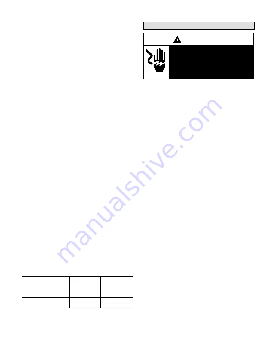
WARNING
Electric shock hazard. Can cause in-
jury or death. Before attempting to
perform any service or maintenance,
turn the electrical power to unit OFF
at disconnect switch(es). Unit may
have multiple power supplies.
At the beginning of each heating or cooling season, check
the system as follows:
Heat Pump Unit
1 − Clean and inspect the outdoor coil. You may flush the
coil with a water hose. Make sure the power is off be-
fore you clean the coil.
2 − The outdoor unit fan motor is pre-lubricated and
sealed. The fan motor requires no more lubrication.
3 − Inspect all connecting lines, joints, and coils for evi-
dence of oil leaks.
4 − Check all wiring for loose connections.
5 − Check for correct voltage at the unit while the unit is
operating.
6 − Check amp draw on the heat pump fan motor.
Unit nameplate__________Actual__________.
7 − Inspect the drain holes in the coil compartment base
and clean them if necessary.
NOTE − If insufficient heating or cooling occurs, gauge the
unit and check the refrigerant charge.
Indoor Coil
1 − If necessary, clean the coil.
2 − Inspect the connecting lines, joints, and coil for evi-
dence of oil leaks.
4 − Check all wiring for loose connections.
5 − Check for correct voltage at the unit.
6 − Check the amp draw on the blower motor.
Motor nameplate__________Actual__________.
3 − Check the condensate line and clean it if necessary.
Indoor Unit
1 − Clean or change the filters.
2 − Lennox blower motors are pre-lubricated and perma-
nently sealed. The blower motor requires no more lu-
brication.
3 − Adjust the blower speed for cooling. Measure the
pressure drop over the coil to determine the correct
blower m
3
/s.
Summary of Contents for HP40
Page 15: ...Page 15...


