background image

Page 11

Diagnostic LEDs

The defrost board uses two LEDs for diagnostics. The

LEDs flash a specific sequence according to the

condition.

TABLE 7

DEFROST CONTROL BOARD DIAGNOSTIC LED
MODE

LED 1

LED 2

Normal Operation/

Power to board

Flash together

with LED 2

Flash together with

LED 1 

Time Delay

To Protect Compressor

Alternating Flashes

with LED 2

Alternating Flashes

with LED 1 

Pressure Switch Open

Off

On

Pressure Switch Lockout On

Off

Board Malfunction

On

On

Ambient Thermistor & Service Light Connection

The defrost control board provides terminal connec

tions for the ambient thermistor and service light.

These features provide a service light thermostat

which activates the room thermostat service light dur

ing periods of inefficient operation. The thermistor

compensates for changes in ambient temperature

which might cause thermostat droop.

MAINTENANCE

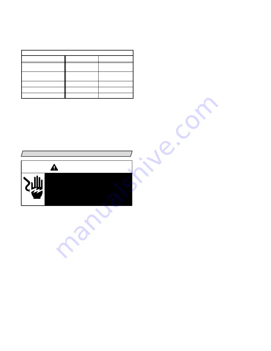
WARNING

Electric shock hazard. Can cause injury

or death. Before attempting to per

form any service or maintenance, turn

the electrical power to unit OFF at dis

connect switch(es). Unit may have

multiple power supplies.

At the beginning of each heating or cooling season, the
system should be cleaned as follows:

Heat Pump Unit

 1- Clean and inspect outdoor coil. (Coil may be

flushed with a water hose.)

 2- Outdoor coil fan motor is prelubricated and

sealed. No further lubrication is needed.

 3- Visually inspect all connecting lines, joints and

coils for evidence of oil leaks.

 4- Check all wiring for loose connections.
 5- Check for correct voltage at unit (unit operating).
 6- Check amp-draw on heat pump fan motor.

Unit nameplate_______Actual_______.

 7- Inspect drain holes in coil compartment base and

clean if necessary.

NOTE-If insufficient heating or cooling occurs, the unit

should be gauged and refrigerant charge checked.

Indoor Coil

 1- Clean coil if necessary.
 2- Check connecting lines, joints and coil for evi

dence of oil leaks.

 3- Check condensate line and clean if necessary.

Indoor Unit

 1- Clean or change filters.
 2- Adjust blower speed for cooling. The pressure drop

over the coil should be checked to determine the cor
rect blower air volume. Refer to the Lennox Engi
neering Handbook for indoor unit blower perfor
mance tables.

 3- Check all wiring for loose connections.
 4- Check for correct voltage at unit.
 5- Check amp-draw on blower motor.

Motor nameplate_______Actual_______.

Summary of Contents for HP-511-513

Page 1: ...evied for non compliance INSTALLATION INSTRUCTIONS HP25 SERIES UNITS HEAT PUMP UNITS 503 302M 6 95 Supersedes 503 247M TABLE OF CONTENTS HP25 HEAT PUMP UNIT 1 SHIPPING AND PACKING LIST 1 GENERAL INFOR...

Page 2: ...D E F G H J K L HP25 211 in 27 7 8 25 7 8 29 7 8 12 1 4 22 7 16 14 7 16 22 1 8 1 7 8 16 3 4 5 1 2 2 7 8 HP25 211 HP25 261 mm 708 657 759 311 570 367 562 48 425 140 73 HP25 311 in 30 7 8 32 1 8 34 1 16...

Page 3: ...OTE 48 1219mm clearance required on top of unit One side dimension may be 12 305mm 36 914mm 36 914mm 36 914mm 36 914mm Heat pump units operate under a wide range of weath er conditions therefore sever...

Page 4: ...is instruction see figure 6 and in indoor unit instructions Refer to figure 5 for thermostat designa tions Refer to unit rating plate for minimum circuit am pacity and maximum fuse size WARNING Unit m...

Page 5: ...1 1 8 in 28 6 mm FIELD FABRICATED L15 LINE SETS L15 41 20 ft 50 ft 6 1 m 15 2 m L15 65 30 ft 50 ft 9 1 m 15 2 m FIELD FABRICATED L15 26 20 ft 50 ft 6 1 m 15 2 m NOTE To obtain maximum efficiency remov...

Page 6: ...o produce substances that corrode copper piping and compressor parts 1 Connect manifold gauge set to the service valve ports as follows low pressure gauge to vapor line service valve high pressure gau...

Page 7: ...and suc tions pressures do not perform normally follow the steps below to correctly phase in the unit 1 Disconnect power to the unit 2 Reverse any two field power leads to the unit 3 Reapply power to...

Page 8: ...6 If ambient temperature is less than 60 F 15 C air flow might need to be restricted to achieve pressur es in the 200 250 psig 1379 1724 kPa range See figure 8 These higher pressures are necessary for...

Page 9: ...ngle pole single throw which is located on the liquid line The switch shuts off the compressor when discharge pressure rises above the factory set ting The switch is normally closed and is permanently...

Page 10: ...PS2 termi nals on the defrost board If using an additional pres sure switch remove jumper before connecting additional switch to control board If no additional switch is needed DO NOT REMOVE JUMPER U...

Page 11: ...power supplies At the beginning of each heating or cooling season the system should be cleaned as follows Heat Pump Unit 1 Clean and inspect outdoor coil Coil may be flushed with a water hose 2 Outdo...

Page 12: ...o City City Serial No Date State State Service Technician Amps Supply Outdoor Fan Compressor Indoor Filter Clean Indoor Blower RPM Electrical Connections Tight Supply Voltage Unit Off S P Drop Over Ev...

Reviews: