Page 12
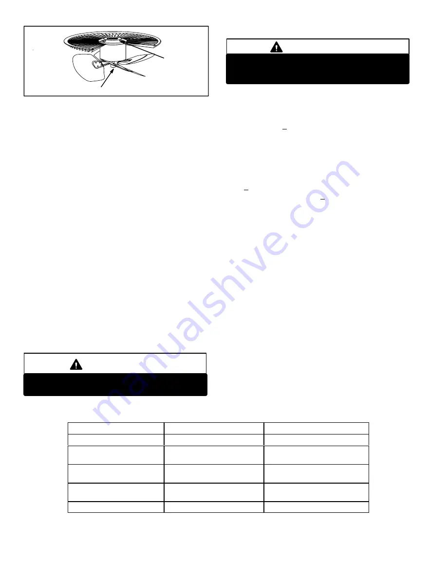
ALIGN FAN HUB FLUSH WITH END OF SHAFT
FIGURE 15
NUTS (4)
D − Reversing Valve L1 and Solenoid
A refrigerant reversing valve with electromechanical so-
lenoid is used to reverse refrigerant flow during unit op-
eration. The reversing valve requires no maintenance. It
is not repairable. If the reversing valve has failed, it must
be replaced.
E − Drier
A filter drier designed for all XP14 model units is factory
installed in the liquid line. The filter drier is designed to re-
move moisture and foreign matter, which can lead to com-
pressor failure.
Moisture and / or Acid Check
Because POE oils absorb moisture, the dryness of the
system must be verified any time the refrigerant sys-
tem is exposed to open air.
A
compressor oil sample must
be taken to determine if
excessive
moisture has been
introduced to the oil. Table 3 lists kits available from Lennox
to check POE oils.
If oil sample taken from a system that has been exposed to
open air does not test in the dry color range, the filter drier
MUST be replace.
To safeguard against moisture entering the system follow
the steps in section IV − sub section B − "Evacuating the
System" when replacing the drier.
IMPORTANT
Replacement filter drier MUST be approved for
HFC−410A refrigerant and POE application.
F − High (S4)/Low (S87) Pressure Switch
IMPORTANT
Pressure switch settings for HFC−410A refrigerant
will be significantly higher than units with
HCFC−22.
An auto-reset, single-pole/single-throw high pressure switch
is located in the liquid line. This switch shuts off the compres-
sor when liquid line pressure rises above the factory setting.
The switch is normally closed and is permanently adjusted to
trip (open) at 590 + 10 psi.
An auto-reset, single-pole/single-throw low pressure
switch is located in the suction line. This switch shuts off the
compressor when suction pressure drops below the factory
setting. The switch is closed during normal operating pres-
sure conditions and is permanently adjusted to trip (open)
at 25 + 5 psi. The switch automatically resets when suction
line pressure rises above 40 + 5 psi. Under certain condi-
tions the low pressure switch is ignored. See
Pressure
Switch Circuit
in the Defrost Control description.
G − Crankecase Heater (HR1) &
Thermostat (S40)
XP14−036, −042, −048 and −060 units are equipped with a 40
watt belly band type crankcase heater. HR1 prevents liquid
from accumulating in the compressor. HR1 is controlled by
a thermostat located on the liquid line. When liquid line tem-
perature drops below 50° F the thermostat closes energiz-
ing HR1. The thermostat will open, de−energizing HR1
once liquid line temperature reaches 70° F.
TABLE 3
KIT
CONTENTS
TUBE SHELF LIFE
10N46 − Refrigerant Analysis
Checkmate−RT700
10N45 − Acid Test Tubes
Checkmate−RT750A (three pack)
2 − 3 years @ room temperature. 3+
years refrigerated
10N44 − Moisture Test Tubes
Checkmate − RT751 Tubes (three
pack)
6 − 12 months @ room temperature. 2
years refrigerated
74N40 − Easy Oil Test Tubes
Checkmate − RT752C Tubes (three
pack)
2 − 3 years @ room temperature. 3+
years refrigerated
74N39 − Acid Test Kit
Sporian One Shot − TA−1


