background image

C


Version: 01.02.2020 
 

E R S A T Z T E I L L I S T E   /   S P A R E   P A R T   L I S T  

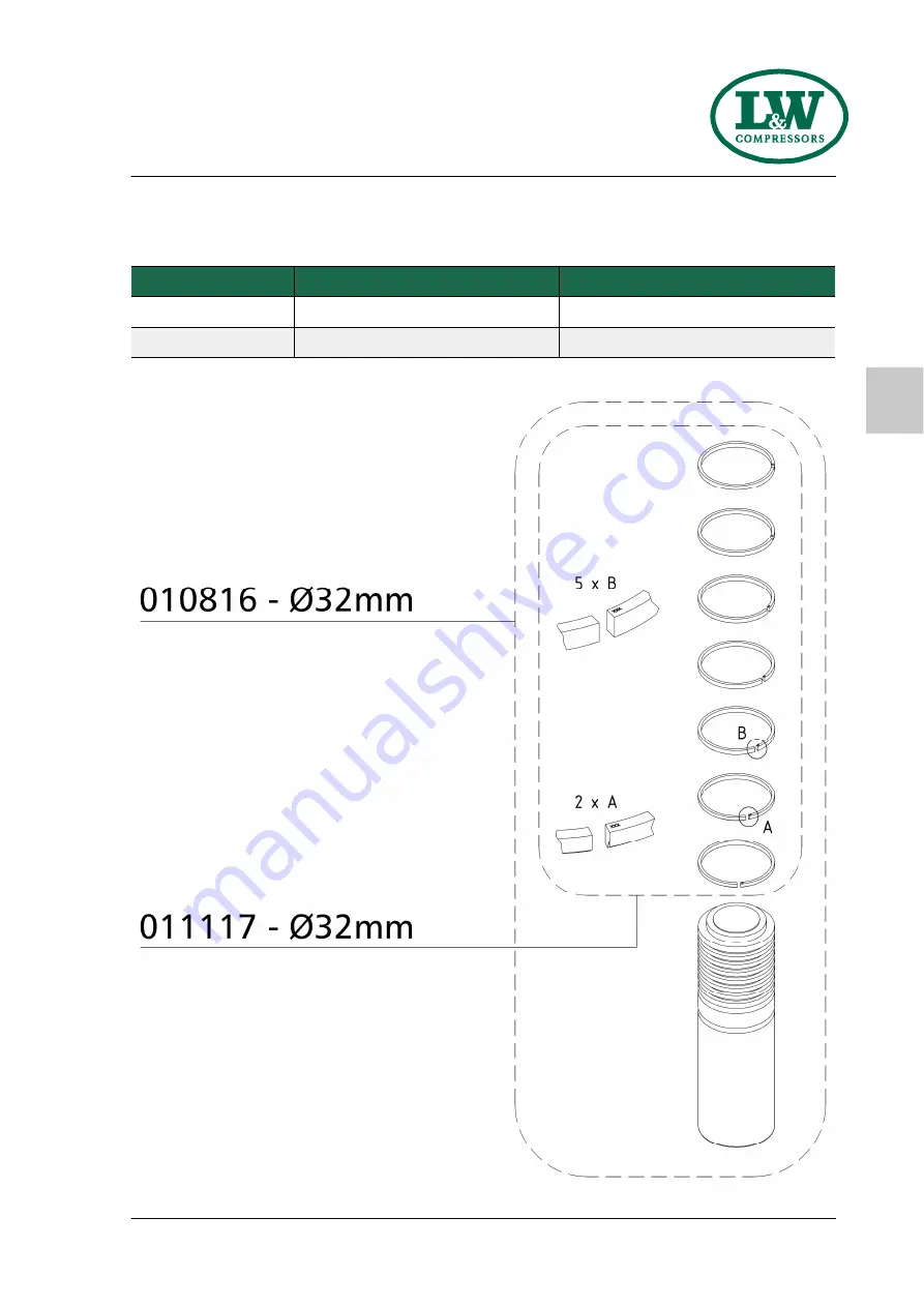
Baugruppe: Kompressionskolben 2. Stufe                                                

Assembly: Compression Piston 2nd Stage 

Best.-Nr. / Order No. 

Benennung


Description


010816 

Kolben 2.Stufe Ø32mm komplett 

Piston 2nd Stage, complete 

011117 

Satz Kolbenringe 2. Stufe / 7Stk. 

Set of Piston Rings, 2nd Stage 

C - 17

LW 150 - 200 ES MC

Summary of Contents for LW 150 ES

Page 1: ...Attachment A B C D E Manufacturer in terms of 97 23 EC The full name and address of the manufacturer is Lenhardt Wagner GmbH An der Tuchbleiche 39 68623 H ttenfeld Germany Phone 49 0 62 56 85 88 0 0 F...

Page 2: ...original invoice Should verifiably defective parts have been delivered we will decide to either replace the parts or repair them The resulting transport and assembly costs will be invoiced No reductio...

Page 3: ...A Operating Instructions Breathing Air Compressor LW 150 ES LW 200 ES Version 31 01 2022...

Page 4: ...ctions 15 Transportation instructions Safety regulations 16 Installation Installation in closed rooms 18 Dimensions 19 Minimum distances 20 Ventilation 21 Electrical Installation 22 23 Operation Impor...

Page 5: ...artridge 53 Filter cartridge change 54 Filter housing Maintenance 55 Inlet filters Inlet filter cartridge change 56 Cylinder heads and valves 57 Replace inlet and outlet valve 1st stage 58 59 Replace...

Page 6: ...from these instructions is excluded from warranty and liability for this product Carry out other commissioning steps only if you have fully understood the following contents Before commissioning and u...

Page 7: ...to shut down also available RTC Remote Tab Control Additional high pressure outlet Power cable and plug Special voltages frequencies on request Electro Motor Powder coated housing in RAL 6026 7016 Sou...

Page 8: ...ing Air Intake Pressure atmospheric Oil Pressure bar 0 6 to 4 0 0 6 to 4 0 0 6 to 4 0 Oil Capacity l 0 8 0 8 1 8 Intake Temperature C 0 45 0 45 0 45 Ambient Temperature C 5 45 5 45 5 45 Cooling Air Vo...

Page 9: ...nation 1 Switchboard 3 Filling pressure gauge 200 bar 4 Lever filling valve 200 bar c w filling hose filling connector 5 Filling pressure gauge 300 bar 6 Lever filling valve 300 bar c w filling hose f...

Page 10: ...LW 150 ES LW 200 ES Version 31 01 22 001 E Page A 8 A Switchboard D E S C R I P T I O N 1 2 3 4 5 No Designation 1 Emergency shut off switch 2 Hour counter 3 ON button 4 OFF button 5 Drain test button...

Page 11: ...nger 18 Hochdruckschlauch HP Hose 19 Sicherheitsventil 3 Stufe Safety Valve 3rd Stage 20 Druckschalter Auto Stopp Pressure Switch Auto Stop 21 l Wasserabscheider 1 7 l Oil Water Separator 1 7 ltr 22 H...

Page 12: ...A S A F E T Y P R E C A U T I O N S...

Page 13: ...the instruction manual is complied with and inspection and maintenance requirements are en forced No change and modification to the unit can be made without the written agreement of the manu facturer...

Page 14: ...A Safety instructions on the unit Importance of notes and warning signs that are affixed to the compressor according to the applica tion or its equipment S A F E T Y P R E C A U T I O N S Warning Hig...

Page 15: ...se this product Comply with all local and national rules and regulations associated with this product Only trained and competent personnel are permitted to inspect repair and service the product Only...

Page 16: ...ensure that the machine is only taken into operation under safe and functional conditions Only operate the compressor if all protective and safety equipment e g detachable protective equipment are pro...

Page 17: ...isplay a warning sign on the main switch The machine and especially the connections and fittings should be cleaned from oil fuel and maintenance products at the beginning of the maintenance repair Do...

Page 18: ...ower Do not stand or work under suspended loads Also separate from minor relocation machinery system of any external energy supply Before recommissioning reconnect the machine to the mains according t...

Page 19: ...A I N S TA L L AT I O N...

Page 20: ...where natural ventilation is not ensured or other systems having high radiation are operating in the same room measures must be taken to provide artificial ventilation Intake air must be free from no...

Page 21: ...LW 150 ES LW 200 ES Version 31 01 22 001 E Page A 19 A I N S T A L L A T I O N Dimensions Fig Dimensions...

Page 22: ...sufficient amount of fresh air available To prevent serious damage ensure that the cooling air flow can flow freely The following minimum distances must be adhered Front side min 1500 mm sides and rea...

Page 23: ...h air available for cooling To prevent serious damage ensure that the cooling air flow can flow freely The necessary cooling air flow can be calculated by using the following formula 300 x drive power...

Page 24: ...ate on the compressor The fusing should be done in accordance with the valid regulations of the responsible electricity supply company When connecting the unit to the electrical supply check the compr...

Page 25: ...nal motor power Fusing start A Connection in mm kw A Direct Star Delta Contactor supply Motor S D 2 2 5 10 1 5 1 5 4 8 5 20 2 5 1 5 5 5 11 3 25 20 2 5 1 5 7 5 15 2 30 25 2 5 1 5 11 21 7 35 4 2 5 15 29...

Page 26: ...A O P E R AT I O N...

Page 27: ...5 A O P E R A T I O N Important operation instructions Note Ensure that all persons handling the compressor are familiar with function and operation of the unit i Wear hearing protection When working...

Page 28: ...the OFF button and contact an authorised electrician 3 Check oil pressure if oil pressure gauge is installed 4 Run the compressor for about 2 minutes 5 Close the open filling valve carefully 6 Run the...

Page 29: ...e oil level reached the middle of the indicated area Warning Check oil level daily Never start the compressor with a too low oil level Risk of accidental loss destruction or deterioration Check V belt...

Page 30: ...ion direction Immediately after switching the compressor on check rotation direction Depending on the place of installation the phase sequence can influence the rotation direction Phase Monitoring Wit...

Page 31: ...Y C O M M I S S I O N I N G Prior to daily operation observe the following Ensure cooling air can flow freely Check compressor oil level by the oil sight glass Check if filter cartridge is in place o...

Page 32: ...rostatic tested check last test date are rated for the final pressure are free from humidity i 1 Close all filling valves 2 Connect the closed compressed air cylinders 3 Open cylinder valves 4 Start c...

Page 33: ...hich automatically shuts down the system when the corresponding final pressure is reached During filling process you can shut down the system at any time by pushing the red button OFF or the emergency...

Page 34: ...A R E M E D Y I N G FA U LT S...

Page 35: ...alve leaky Replace Pipes heat exchanger broken Replace Condensate drain valves leaky Unscrew valves check sealing surfaces clean replace if necessary Final pressure switch stop unit Verify settings re...

Page 36: ...diameter Wrong compressor rotation direction Ensure correct phase rotation observe rotation direction arrow Inlet and outlet valves contaminated defective Clean replace if necessary Safety valve leaks...

Page 37: ...medy Pressure stages are not as prescribed control pressure of pneumatic condensate valve too low Check corresponding inlet and outlet valve re place if necessary Piston sealing of pneumatic condensat...

Page 38: ...cartridge already partly saturated before change Store filter cartridges properly dispose defective cartridges Cylinder s piston s or piston ring s defective Replace Operating temperature too high Ens...

Page 39: ...A M A I N T E N A N C E A N D S E R V I C E...

Page 40: ...only be carried out by trained personnel This is necessary because all maintenance work can not be explained exactly and detailed in this manual Only use authentic spare parts for service work Danger...

Page 41: ...ridge lifetime Operate unit to final pressure and check function of final pressure switch Every 3 months or as required Maintenance work Type Quantity Order No Check Retorque all connections and bolts...

Page 42: ...lly Maintenance work Type Quantity Order No Oil change if less than 1000 operating hours 0 8 000001 Check V belt tension and condition LW 150 ES MC 50Hz 1 001685 LW 200 ES MC 50Hz 1 001685 LW 250 ES M...

Page 43: ...1224 Replace sintered metal filter of oil separator 2 Stufe 1 002123 Replace o ring of the water separator 2 Stufe 1 001255 Replace o ring of condensate stop valve 1 001264 Replace sintered metal filt...

Page 44: ...of our 2000h service kits You can find an overview on page Service Kits i Maintenance work Type Quantity Order No Replace o rings and gaskets of 1st 2nd and 3rd stage O Ring 1st stage 1 011104 O Ring...

Page 45: ...d and gives assurance that all parts are included in the order Depending on the model and interval the service kits include parts such as O Rings Sinter Filter Inlet Filter Silencers In Outlet Valve V...

Page 46: ...1 Tighten V belt by the lock nuts Fig 2 3 Tighten mounting screws Fig 1 ATTENTION Motor plate A and motor B must be mounted in parallel Fig 4 Correct V belt tension Do not tension V belts too tight Th...

Page 47: ...operation of the system The oil level should be between the middle and upper end of the oil sight glass Never start the compressor with a too low oil level Refill new compressor oil at least when the...

Page 48: ...The oil level should be between the middle and upper end of the oil sight glass Screw oil fill port manually in and tighten by hand The oil change is now completed Maintenance intervals First oil cha...

Page 49: ...screw clockwise Reducing cut out pressure Turn the adjusting screw anti clockwise Adjust the pressure switch in steps of a quarter turn Restart the compressor after every adjustment step to verify th...

Page 50: ...electronic timer controlled solenoids The timer is located in the switch box and activates the dump valves about every 15 minutes To release the complete condensate through the black plastic hoses we...

Page 51: ...r Remove sinter filter holder Fig 2 Change sinter filter Fig 3 screw in new sinter filter by using a suitable screwdriver Change o ring previously grease new o ring Fig 4 Place sinter filter holder in...

Page 52: ...tridges are factory vacuum sealed We recommend unpacking the filter cartridges just before installation Filter cartridges which are exposed too long could be saturated with moisture and become unusabl...

Page 53: ...ousing Fig 3 Open the packing of the new filter cartridge and place it with the filter tool in the filter housing Screw the new filter cartridge hand tight in by using the filter tool Screw the cover...

Page 54: ...ismount filter housing Loosen pipe connections and nuts Fig 3 Remove filter housing Dismount filter housing base Change o ring and back up ring previously grease both Fig 4 Screw filter base tight in...

Page 55: ...ew o ring Fig 3 Push the condensate stop valve into the filter housing by using a threated rod Change o ring of the cover previously grease new o ring Fig 4 Mount the cover tighten the allen bolts cro...

Page 56: ...s follows Loosen pipe connections and mounting screws Remove pneumatic condensate valve Loosen connection Fig 2 Change sinter filter Fig 3 Tighten horizontal screw Mount pneumatic condensate valve Tig...

Page 57: ...ridge and assemble the housing Place o ring into the groove Fig 4 Place and align the filter housing carefully inlet port up hose connector 90 turned to the left Fig 5 Tighten mounting screw and conne...

Page 58: ...ons Dismount valve heads to change valves The three valves are combined inlet and outlet valves The first stage is a plate valve The stages two and three are made of a spring operated piston which act...

Page 59: ...valve Remove spring wire clamps of the crankcase ventilation hose Fig 1 Remove hose Loosen pipe connections Loosen valve head screws Remove valve head and check if defective Remove upper valve head g...

Page 60: ...ole and valve head locating pin Fig 2 3 Place valve head carefully on top of the cylinder take care to keep valve in place Fig 4 Tighten valve head screws crosswise Set tight connecting nut and fix ve...

Page 61: ...ut It can still stick inside the cylinder head Remove inlet outlet valve Check valve head if defective check locating pin Change upper valve gasket Change lower valve gasket aluminium gasket Insert ne...

Page 62: ...seals to avoid manipulation of the limit value settings Safety valves with removed seals have to be immediately checked for the prescribed settings and replaced if necessary The safety valve of the f...

Page 63: ...maintaining the valve prevents the compressed air from blowing off final pressure gauge 0 bar When the adjusted opening pressure is reached 150 and 180 bar the purified compressed air flows via pressu...

Page 64: ...ressor Watch the final pressure gauge The safety valve should open when reaching working pressure of the compressor If not switch off the unit and take out of service until the safety valve has been r...

Page 65: ...ssor Switch off the compressor at a pressure of approx 150 bar Verify the compressor for release noises A slight hiss of the air inlet filter nozzle can be ignored If release noises occur localise blo...

Page 66: ...1000 result Test is applicable Example Filter housing 2 3 l Maximum operating pressure 350 bar Content volume 2 3 litres 350 bar x 2 3 litres 805 805 is smaller than 1000 result Test is applicable Pr...

Page 67: ...A M A I N T E N A N C E R E C O R D S...

Page 68: ...urname Name Date Place Signature Instructor By adding themselves to this list the person that signs it confirms having been given a yearly introduction instruction about the function and operation of...

Page 69: ...LW 150 ES LW 200 ES Version 31 01 22 001 E Page A 67 A M A I N T E N A N C E R E C O R D S Top up oil oil change Date Operating hours Oil quantity l Name...

Page 70: ...LW 150 ES LW 200 ES Version 31 01 22 001 E Page A 68 A M A I N T E N A N C E R E C O R D S Cartridge change Date Operating hours Difference Name...

Page 71: ...LW 150 ES LW 200 ES Version 31 01 22 001 E Page A 69 A M A I N T E N A N C E R E C O R D S Maintenance work Description Date signature...

Page 72: ...LW 150 ES LW 200 ES Version 31 01 22 001 E Page A 70 A M A I N T E N A N C E R E C O R D S Replaced Parts Designation Part number Date signature...

Page 73: ...rain valves Store the compressor in a cool dry place free from dust and contamination A dust cover is recommended as long as condensation can be avoided If compressor unit should be stored for a perio...

Page 74: ...hen recommissioning proceed according to the operating instructions Disposal The product must be disposed in accordance with national waste disposal regulations and by an appropriate waste disposal co...

Page 75: ...C ERSATZTEILLISTEN SPARE PARTS LISTS DETAILANSICHTEN DETAILED VIEWS...

Page 76: ...18 Saug Druckventil 2 Stufe In Outlet Valve 2nd Stage 19 Saug Druckventil 3 Stufe In Outlet Valve 3rd Stage 20 K hler Cooler 21 l Wasserabscheider Oil Water Separator 23 Filtergeh use 1 7 l Filter Ho...

Page 77: ...Inhaltsverzeichnis Kondensat Sammelbeh lter Condensate Catch Tank 46...

Page 78: ...45mm 005839 Linsenflanschschraube mit Innensechs kant M6x25 mm DIN 7380F 10 9 Flange Button Head Screw M6x25 mm DIN 7380F 10 9 005841 Linsenflanschschraube mit Innensechs kant M6x20 mm DIN 7380F 10 9...

Page 79: ...Best Nr Order No Benennung Description 011761 Kompressor Motorplatte Baueinheit Compressor Motor Plate Unit 011762 Luftleitblech L fterrad Fan Flywheel Panel 011888 Schalld mmmatten LW 150 200 ES Sou...

Page 80: ...C Version 10 09 2021 D E T A I L A N S I C H T D E T A I L E D V I E W Baugruppe Geh use Assembly Housing C 3 LW 150 200 ES MC...

Page 81: ...C Version 10 09 2021 D E T A I L A N S I C H T D E T A I L E D V I E W Baugruppe Geh use Assembly Housing C 4 LW 150 200 ES MC...

Page 82: ...mm c w nuts olive seals 012076 Rohrleitung 8mm komplett mit M S Pipe 8mm c w nuts olive seals 012077 Rohrleitung 8mm komplett mit M S Pipe 8mm c w nuts olive seals 012067 Rohrleitung 8mm komplett mit...

Page 83: ...C Version 27 01 2022 D E T A I L A N S I C H T D E T A I L E D V I E W Baugruppe Rohrleitungssystem F llventile Assembly Pipework Filling Valves C 6 LW 150 200 ES MC...

Page 84: ...3mm c w fixing strap 009683 Verschraubung mit fester Mutter EGE 08L RED G1 4 Connection with fixed nut EGE 08L RED G1 4 012075 Rohrleitung 8mm komplett mit M S Pipe 8mm c w nuts olive seals 012076 Roh...

Page 85: ...C Version 10 09 2021 D E T A I L A N S I C H T D E T A I L E D V I E W Baugruppe Rohrleitungssystem F llventile Assembly Pipework Filling Valves C 8 LW 150 200 ES MC...

Page 86: ...C Version 10 09 2021 D E T A I L A N S I C H T D E T A I L E D V I E W Gesamtansicht Verdichtereinheit Overall View Compressor Assembly C 9 LW 150 200 ES MC...

Page 87: ...Screw 001081 6 kant Schraube M8x20mm Hexagon Screw 001082 6 kant Schraube M8x25mm Hexagon Screw 001159 Stoppmutter M8 Lock Nut 001164 Stoppmutter M10 Lock Nut 001181 U Scheibe A8 Washer 001186 U Sche...

Page 88: ...ge 40mm Double Nipple 011092 lschauglas mit Dichtung G3 4 Oil Level Indicator c w gasket 011103 O Ring 81x2mm O ring 011104 O Ring 84x2mm O ring 011105 O Ring 50x2mm O ring 011106 Anschlussadapter Kur...

Page 89: ...C Version 10 09 2021 D E T A I L A N S I C H T D E T A I L E D V I E W Baugruppe Kompressorblock Assembly Compressor Block C 12 LW 150 200 ES MC...

Page 90: ...gsring Circlip A30 001365 Sicherungsring Circlip I35 010112 Passfeder Woodruff Key 010809 Kurbelgeh use Crankcase 010818 Pleuel 1 Stufe Con Rod 010823 Kurbelwelle Crankshaft 010824 Gegengewicht Untert...

Page 91: ...C Version 01 02 2020 D E T A I L A N S I C H T D E T A I L E D V I E W Baugruppe Kurbeltrieb Assembly Crank Drive C 14 LW 150 200 ES MC...

Page 92: ...l Side Best Nr Order No Benennung Description 001361 Sicherungsring I70 Circlip 010279 Sicherungsring I62 Circlip 010785 O Ring 128x2mm O Ring 010821 Lagerdeckel Bearing Cover Flywheel Side 010831 Wel...

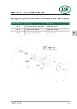
Page 93: ...ringe 75 5mm 1 Stufe Set Piston Rings 1st Stage 000051 Satz Kolbenringe 72mm 1 Stufe Set Piston Rings 1st Stage 010814 Kolben 1 Stufe 75 5mm komplett Piston 1st Stage complete 010815 Kolben 1 Stufe 80...

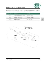
Page 94: ...I S T Baugruppe Kompressionskolben 2 Stufe Assembly Compression Piston 2nd Stage Best Nr Order No Benennung Description 010816 Kolben 2 Stufe 32mm komplett Piston 2nd Stage complete 011117 Satz Kolben...

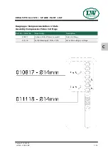
Page 95: ...T L I S T Baugruppe Kompressionskolben 3 Stufe Assembly Compression Piston 3rd Stage Best Nr Order No Benennung Description 010817 Kolben 3 Stufe 14mm komplett Piston 3rd Stage 011118 Satz Kolbenring...

Page 96: ...ppe Saug Druckventil 2 Stufe Assembly In Outlet Valve 2nd Stage Best Nr Order No Benennung Description 000532 Ventildichtung Saug Druckventil unten Lower Valve Gasket 000541 Dichtring Dichtung Ventil...

Page 97: ...e Saug Druckventil 3 Stufe Assembly In Outlet Valve 3rd Stage Best Nr Order No Benennung Description 000534 Ventildichtung Saug Druckventil Lower Valve Gasket 000541 Dichtring Dichtung Ventil Upper Al...

Page 98: ...01030 Zylinderschraube M6x16mm Allen Bolt 001047 Zylinderschraube M6x12mm Allen Bolt 001848 Rohrschelle 15 18mm Pipe Clamp 8mm Finned Pipe 009564 Rohrschelle 21 12 breit Pipe Clamp 010396 K hler 1 Stu...

Page 99: ...C Version 27 01 2022 D E T A I L A N S I C H T D E T A I L E D V I E W Baugruppe K hler Assembly Cooler C 22 LW 150 200 ES MC...

Page 100: ...WE 12L R3 8 Elbow Connection 000837 Verschlussstopfen G1 8 Plug 000863 Winkelverschraubung WE 18L R1 2 Elbow Connection 001255 O Ring 26x2mm O Ring 002123 Sinterfilter G3 8 AG Sinter Filter 002128 Wa...

Page 101: ...C Version 10 09 2021 D E T A I L A N S I C H T D E T A I L E D V I E W Baugruppe l Wasserabscheider Assembly Oil Water Separator C 24 LW 150 200 ES MC...

Page 102: ...G1 4 08L 001159 Stoppmutter M8 DIN985 ZN Lock Nut M8 DIN985 ZN 001181 U Scheibe A8 DIN125 ZN Washer A8 DIN125 ZN 001285 St tzring 63 96x4 65 NBR90 350 bar Back up Ring 63 96x4 65 NBR90 350 001287 O R...

Page 103: ...C Version 10 09 2021 D E T A I L A N S I C H T D E T A I L E D V I E W Filtergeh use 1 7 l Filter Housing 1 7 ltr C 26 LW 150 200 ES MC...

Page 104: ...2 Doppelnippel G1 8 1 4 Double Nipple G1 8 1 4 001011 Zylinderschraube Allen Bolt 001546 Aludichtring f r Magnetventile G1 4 19 x 12 3 x 5mm Alloy Seal Ring for G1 4 male 19 x 12 3 x 5mm 005325 Versch...

Page 105: ...Version 27 01 2022 C D E T A I L A N S I C H T D E T A I L E D V I E W Pneum Kondensat Ablassventil Pneumatic Condensate Valve C 28 LW 150 200 ES MC...

Page 106: ...3 NBR70 O Ring 38 x 3 NBR70 006370 Geh use Kondensat Stopp Ventil Housing Condensate Stop Valve 006372 Ventilkegel Kondensat Stopp Ventil Valve Condensate Stop Valve 006373 Stauscheibe Kondensat Stopp...

Page 107: ...C Version 10 09 2021 D E T A I L A N S I C H T D E T A I L E D V I E W Baugruppe Kondensat Stopp Ventil Assembly Condensate Stop Valve C 30 LW 150 200 ES MC...

Page 108: ...e S8 N0110 ZN Clamp Washer S8 S8 N0110 ZN 002914 Sinterfilter f r Wasserabscheidersockel M12x1 5mm AG Sintered filt water sep Base M12x1 5mm AG 006368 Beh lter Kondensat Stopp Ventil Container Condens...

Page 109: ...C Version 10 09 2021 D E T A I L A N S I C H T D E T A I L E D V I E W Baugruppe Kondensat Stopp Ventil Geh use Assembly Housing Condensate Stop Valve C 32 LW 150 200 ES MC...

Page 110: ...apter 000514 Stift Druckhalte R ckschlagventil Stud PMV 000515 Geh use Druckhalte R ckschlagventil Main Body PMV 000516 Nutring Druckhalter ckschlagventil 5 x 10 x 5 2 5 90 Blau Seal Ring PMV 5 x 10 x...

Page 111: ...D E T A I L E D V I E W Druckhalteventil Pressure Maintaining Valve 000514 Repair kit 003548 Consists of Yellow marked P N s Reparatursatz 003548 Bestehend aus Gelbmarkierte Bestellnummern 000516 000...

Page 112: ...No Benennung Description 000203 Druckschalter 50 350 bar Pressure Switch 50 350 bar 000757 T Verschraubung mit fester Mutter seitl EL 08 L T Connection with fixed nut EL 08 L 009683 Verschraubung mit...

Page 113: ...C Version 10 09 2021 D E T A I L A N S I C H T D E T A I L E D V I E W Druckschalter Pressure Switch C 36 LW 150 200 ES MC...

Page 114: ...00557 Sicherheitsventil 350bar mit T V Safety Valve 350bar c w T V 000738 Verschraubung GE08LRCFX Connection GE08LRCFX 000761 Winkelverschraubung WE08LRA3CX Elbow Connection WE08LRA3CX 001044 Zylinder...

Page 115: ...C Version 10 09 2021 D E T A I L A N S I C H T D E T A I L E D V I E W Sicherheitsventil Safety Valve C 38 LW 150 200 ES MC...

Page 116: ...Stoppmutter M10 Lock Nut 001186 U Scheibe A10 Washer 001211 Passfeder DIN6885 A10X8X56mm Woodruff Key DIN6885 A10X8X56mm 001828 U Scheibe A10 5 Washer 008644 Spannbuchse 28mm Clamp sleeve for pulley...

Page 117: ...C Version 10 09 2021 D E T A I L A N S I C H T D E T A I L E D V I E W Baugruppe Motor Assembly Engine C 40 LW 150 200 ES MC...

Page 118: ...errad Assembly Flywheel Assembly Best Nr Order No Benennung Description 001043 Zylinderschraube M8x35 Allen Bolt 001184 Schnorr Scheibe S8 Clamp Washer 003983 Scheibe Schwungrad Washer Flywheel 010898...

Page 119: ...mpfer Kipphebelventil G1 8 Silencer Lever Filling Valve G1 8 003493 Faltenbalg Kipphebelventil schwarz Gaiter lever valve black 003494 Faltenbalg Kipphebelventil rot Gaiter lever valve red 003778 Kipp...

Page 120: ...C Version 10 09 2021 D E T A I L A N S I C H T D E T A I L E D V I E W F llventile mit Schl uchen Filling valves with hoses C 43 LW 150 200 ES MC...

Page 121: ...200bar 000697 F llanschluss o Handrad 300bar Filling Connector w o handwheel 300bar 000701 Sicherheitsf llanschluss ohne Handrad 200bar Anti Whip Connector w o handwheel 200bar 000702 Sicherheitsf lla...

Page 122: ...C Version 28 05 2013 D E T A I L A N S I C H T D E T A I L E D V I E W F llanschl sse Filling connectors C 45 LW 150 200 ES MC...

Page 123: ...Condensate Catch Tank 10 Litre 006379 Zugfeder Kondensatfilterpatrone Spring Condensate Filter Cartr 006460 Federspannblech Kondensatbeh lter Spring Clamping Plate CCT 006461 Halteblech Kondensatbeh...

Page 124: ...C Version 10 09 2021 D E T A I L A N S I C H T D E T A I L E D V I E W Baugruppe Kondensat Sammelbeh lter Assembly Housing Condensate Catch Tank C 47 LW 150 200 ES MC...

Page 125: ...D O P T I O N S...

Page 126: ...Filling Pressure Operation 9 Interstage Pressure Gauge 13 Oil Pump 17 Oil Pressure Gauge 21 Oil Pressure Monitoring 24 Oil Temperature Monitoring 28 Cylinder Head Temperature Monitoring 31 2 3 ltr fin...

Page 127: ...D A U T O S T A R T F U N C T I O N D 1 LW 150 200 ES...

Page 128: ...he selec ted minimum pressure the unit automatically restarts To enable a manual start shut off automatic operation by pushing the Stop button Start button lamp goes out Now turn selector switch to se...

Page 129: ...ck last test date are rated for the final pressure are free from humidity i 1 Turn selector switch to semi automatic mode 2 Close all filling valves 3 Connect closed compressed air cylinders 4 Open fi...

Page 130: ...ly 8 Close and vent all filling valves 9 Disconnect all compressed air cylinders from filling valves 10 If automatic operation is interrupted by pushing the OFF button turning the selector switch trip...

Page 131: ...t Nr Order No Benennung Description 000203 Druckschalter Pressure Switch 000751 T Verschraubung 8L T Piece 8L 000765 Schneidring 8L Olive Seal 8L 004691 Wahlschalter Selector switch 005663 Einlegeschi...

Page 132: ...C A D D I T I O N A L F I L L I N G H O S E D 6 LW 150 200 ES...

Page 133: ...000773 Manometerverschraubung IG 1 4 MAVE 08 LR mit fester NMutter Connection Pressure GaugeIG 1 4 MAVE 08 LR c w fixed nut 000777 Dichtring f r Manometerverschraubung DKI1 4CFX Seal Ring for Pressure...

Page 134: ...C Version 10 09 2021 A D D I T I O N A L F I L L I N G H O S E D 8 LW 150 200 ES...

Page 135: ...D 2 0 0 3 0 0 B A R PA R A L L E L F I L L I N G P R E S S U R E O P E R AT I O N D 9 LW 150 200 ES...

Page 136: ...he compressor is equipped with a pressure re ducer a second final pressure safety valve and a second fil ling pressure gauge The handwheels or gaiters are colour coded to allow an opti cal differentia...

Page 137: ...w fixed nut 000777 Dichtring f r Manometerverschraubung DKI1 4CFX Seal Ring for Pressure Gauge DKI1 4CFX 001156 Stoppmutter M6 DIN985 ZN Lock Nut M6 DIN985 ZN 001428 Druckminderer High Flow einstellba...

Page 138: ...D Version 10 09 2021 200 300 BAR PARALLEL FILLING PRESSURE OPERATION Verrohrung 2 Druckbereiche Spare Part List Piping 2 Pressure Ranges D 12 LW 150 200 ES...

Page 139: ...D I N T E R S TA G E P R E S S U R E G A U G E D 13 LW 150 200 ES...

Page 140: ...le pressure gauge This is serviceable for trou bleshooting and allows detecting faults at an early stage Indicated interstage pressures depend on final pressure settings The pressure gauges should sho...

Page 141: ...ennung Description 000660 Manometer 0 60 bar Pressure Gauge 0 60 bar 000663 Manometer 0 400 bar Pressure Gauge 0 400 bar 000710 Verschraubung 1 8 6L Connection 1 8 6L 001445 6L Manometerschlauch 600 m...

Page 142: ...D Version 10 09 2021 I N T E R S T A G E P R E S S U R E G A U G E Spare part lists 002507 000660 000663 000710 001445 001445 001445 D 16 LW 150 200 ES...

Page 143: ...D O I L P U M P D 17 LW 150 200 ES...

Page 144: ...e gaskets with oil before placing respect mounting direction Be sure to position the arrow from the new oil sieve opposite to inlet and return ports of the pump see Fig 2 Remount the cover with the 4...

Page 145: ...g Copper Seal Ring 002340 O Ring lpumpenflansch O Ring oil pump flange 005272 Hohlschraube G1 4 AG Banjo Bolt G1 4 male 010785 O Ring O Ring 010820 Lagerdeckel Bearing Cover Oil Pump Side 010822 lpump...

Page 146: ...D Version 10 09 2021 Detailed View O I L P U M P D 20 LW 150 200 ES...

Page 147: ...D O I L P R E S S U R E G A U G E D 21 LW 150 200 ES...

Page 148: ...direction see rotation direction arrow Oil level too low not enough oil in the compressor Oil pump filter contaminated Oil intake pipe damaged defective Oil temperature below 5 C lubrication not possi...

Page 149: ...t lists Best Nr Order No Benennung Description 001447 Manometerschlauch 800mm Hose for Pressure Gauge 800mm 002507 ldruckmanometer 0 10bar Oil Pressure Gauge 0 10bar O I L P R E S S U R E G A U G E 00...

Page 150: ...D O I L P R E S S U R E M O N I T O R I N G D 24 LW 150 200 ES...

Page 151: ...ssure of 0 5 bar The red warning lamp Oil Pressure Monitoring lights up Possible causes of fault Wrong compressor rotation direction see rotation direction arrow Oil level too low not enough oil in th...

Page 152: ...ection w o nut olive seal 001022 Zylinderschraube M5x45mm Allen Bolt 001152 Stoppmutter M5 Lock Nut 001176 U Scheibe A5 Washer 005261 Druckschalter inkl Stecker Oil Pressure Switch 0 2 2 bar 008995 Wi...

Page 153: ...06L Connection with fixed nut 001022 Zylinderschraube M5x45mm Allen Bolt 001152 Stoppmutter M5 Lock Nut 001176 U Scheibe A5 Washer 005261 Druckschalter inkl Stecker Oil Pressure Switch 0 2 2 bar 00899...

Page 154: ...D O I L T E M P E R A T U R E M O N I T O R I N G D 28 LW 150 200 ES...

Page 155: ...peration The compressor automatically shuts off when oil tempera ture exceeds the maximum pressure of 100 C The red warning lamp Oil Temperature Monitoring lights up Possible causes of fault Ambient t...

Page 156: ...09 2021 O I L T E M P E R A T U R E M O N I T O R I N G Spare part lists Best Nr Order No Benennung Description 004342 Display Display 004730 Display und Sensor Display and Sensor 004342 004730 D 30 L...

Page 157: ...D C Y L I N D E R H E A D T E M P E R AT U R E M O N I T O R I N G D 31 LW 150 200 ES...

Page 158: ...stage during operation The compressor shuts off automatically when cylinder head temperature exceeds the maximum pressure of 120 C The red warning lamp Cylinder Head Tem perature Monitoring lights up...

Page 159: ...10 09 2021 C Y L I N D E R H E A D T E M P E R A T U R E M O N I T O R I N G Spare part lists Best Nr Order No Benennung Description 004726 Display Display 005585 Sensor Sensor 004726 005585 D 33 LW 1...

Page 160: ...D F I N A L F I LT E R S E PA R A T O R 2 3 LT R D 34 LW 150 200 ES...

Page 161: ...egrated breathing air purification system Air is compressed up to 350 bar dried and odour and tasteless purified Oil residues are bounded The breathing air filter cartridge consists of a molecular sie...

Page 162: ...essure Gauge G1 4 08L 001159 Stoppmutter M8 DIN985 ZN Lock Nut M8 DIN985 ZN 001181 U Scheibe A8 DIN125 ZN Washer A8 DIN125 ZN 001285 St tzring 63 96x4 65 NBR90 350 bar Filtergeh use Back up Ring 63 96...

Page 163: ...Version 10 09 2021 D F I N A L F I L T E R S E P A R A T O R 2 3 L T R Spare Part List D 37 LW 150 200 ES...

Page 164: ...of the new filter cartridge and place it with the filter tool in the filter housing Screw the new filter cartridge hand tight in by using the filter tool Screw the cover of the filter housing first m...

Page 165: ...ng Loose pipes and nuts Fig 3 Remove filter housing Dismount filter housing base Change o ring and back up ring previously grease both Fig 4 Screw filter base tight in Mount filter housing Connect pip...

Page 166: ...A N C E A N D S E R V I C E Every 1000 operating hours Maintenance work Type Quantity Order No Replace o ring of the 2 3 ltr final filter tower 2 001287 Replace back up ring of the 2 3 ltr final filte...

Page 167: ...C A D D I T I O N A L H I G H P R E S S U R E O U T L E T D 41 LW 150 200 ES...

Page 168: ...DCF Reducer with fixed nut RED10 08LOMDCF 000902 Winkelschottverschraubung WSV10LOMDCF Elbow Bulkhead Fitting WSV10LOMDCF 001199 U Scheibe A17 DIN 125 ZN ISO 7090 Washer A17 DIN 125 ZN ISO 7090 012096...

Page 169: ...C Version 10 09 2021 A D D I T I O N A L H I G H P R E S S U R E O U T L E T Spare Part Lists D 43 LW 150 200 ES...

Page 170: ...D A I R C O O L E R C O N N E C T I O N K I T D 44 LW 150 200 ES...

Page 171: ...and connect the air cooler according to the connection designation inlet outlet To operate the unit without air cooler reinstall the U connection and the compressor is ready for use Air cooler connec...

Page 172: ...021 Spare part lists Best Nr Order No Benennung Description 000902 Schottverschraubung Elbow Bulkhead Fitting 006860 Rohrbogen U Connection 006860 A I R C O O L E R C O N N E C T I O N K I T 000902 D...

Page 173: ...E A T T A C H M E N T Version 11 12 E...

Page 174: ...ssure 160 350 bar 1 100 l min Suitable media Media resistant non corrosive gases The safety valve is used for protection of pressurized components eg pipelines pressure vessels or the compressor itsel...

Page 175: ...e problem is on the system A constant blowing of the safety valve is not permitted the sealing seat of the valve can be damaged The error on the system must be detected and repaired before further fil...

Page 176: ...ately Notes The safety valve must be installed directly on the protected pressure vessel and or the plant The safety valve must be installed in an upright position The flow area of the port must be gr...

Page 177: ...INFORMATIONON THE SERVICE LIFE OF L W HIGH PRESSURE HOSES...

Page 178: ...bly and before commissioning 3 Recurring test 4 Procedure for hose lines found to be defective 4 Test intervals 4 Persons qualified to test hose lines 5 Maintenance Replacing hose lines 6 Immediate re...

Page 179: ...regarding type scope and deadlines as well as the replacement intervals must be documented in writing as occupational health and safety measures The results of the tests must also be recorded e g tog...

Page 180: ...replaced at the same time precautions must be taken to prevent mix ups of the connections or the installation points Test intervals Deadlines for the recurring tests of the hose lines should already b...

Page 181: ...t be sufficiently familiar with the conditions that demand the performance of tests such as the result of the risk assessment or observations during the working day there is proof of recent profession...

Page 182: ...ite properties and reduces the performance of the hose lines This limits the service life of a hose line and the operator must ensure that hose lines are replaced at appropriate intervals Immediate re...

Page 183: ...e guideline given above for a replacement interval of six years for hose lines meeting normal requirements includes a maximum storage period of two years The guideline value of two years for hose line...

Page 184: ...void storage temperatures below 10 C for elastomers Do not use ozone generating light fittings or electrical devices that may produce sparks in the immediate vicinity Ozone generating light fittings a...

Page 185: ...ANNEX...

Page 186: ...he hose is routed via a kink protector if necessary on the connecting element sufficient clearance prevents external mechanical influences or abrasion on the edges hose bridges prevent damage being ca...
Page 187: ...arried out before the functional test All parts of the system must be tested at least at the maximum working pressure that could be achieved taking into account all intended applications Are the hose...

Reviews: