®
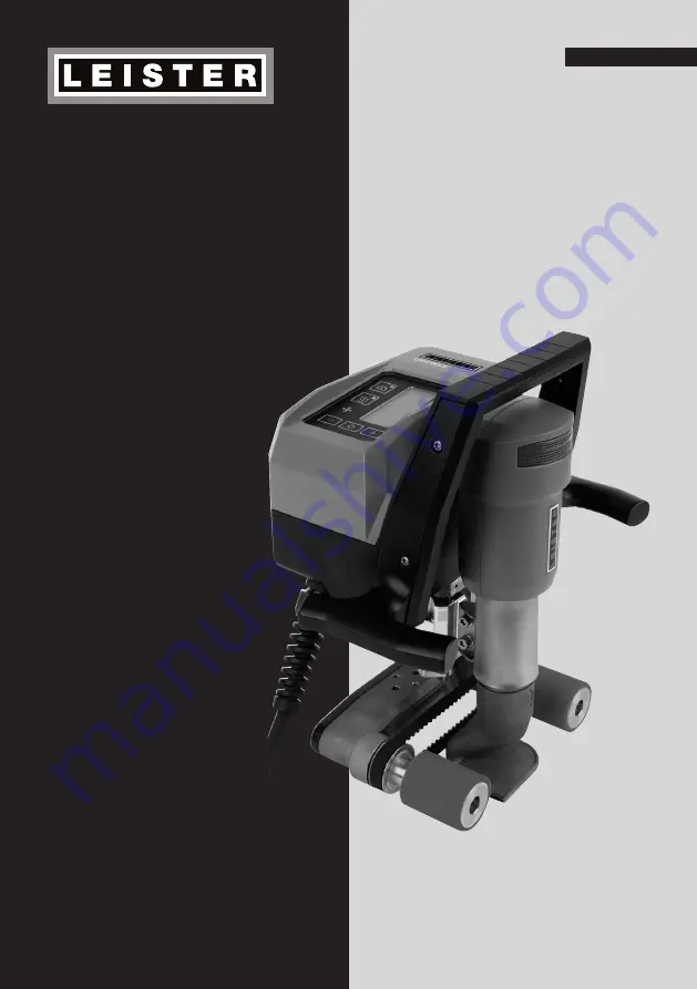
UNIDRIVE
500
Leister Technologies AG
Galileo-Strasse 10
CH-6056 Kaegiswil, Switzerland
Tel.
+41 41 662 74 74
Fax +41 41 662 74 16
www.leister.com
[email protected]
English
Page 1: ... UNIDRIVE 500 Leister Technologies AG Galileo Strasse 10 CH 6056 Kaegiswil Switzerland Tel 41 41 662 74 74 Fax 41 41 662 74 16 www leister com sales leister com English ...
Page 2: ...ick Guide UNIDRIVE 500 13 7 1 Switching on Starting 13 7 2 Switching off 13 8 Operating unit UNIDRIVE 500 13 8 1 Function keys 13 8 2 Display 14 8 3 Display symbols of the status display Display 20 15 8 4 Display symbols for the welding speed Display 21 15 8 5 Display symbols for the welding temperature Display 22 15 8 6 Display symbols for the air volume Display 23 15 8 7 Status LED display 15 9 ...
Page 3: ...g high quality materials For further information on the UNIDRIVE 500 visit www leister com The UNIDRIVE 500 is intended for professional use on flat and sloping roofs certain geosynthetic applications and the swimming pool market Welding processes and types of materials Overlap welding of thermoplastic elastomer membranes such as TPO FPO PVC ECB modified EPDM EVA PIB PMI PO PP Overlap welding for ...
Page 4: ...t box included with the delivery see scope of delivery 5 4 2 and carry the transport box by the handle provided The hot air blowers 6 MUST be allowed to cool down prior to transport Never store flammable materials such as plastic wood or paper in the trans port box Never use the carrying handle 4 on the device or on the transport box for transporting with a crane To manually raise the semi automat...
Page 5: ...tions and always reference it when addressing queries to our representatives or authorized Leister Service Centers Model Serial no Standard equipment in the case 1x UNIDRIVE 500 drive 1x wire brush 1x hexagon wrench key size 3 1x quick guide 1x safety instructions 4 Your UNIDRIVE 500 4 1 Type plate and identification 4 2 Scope of delivery ...
Page 6: ...s 1 Power cord 2 Housing 3 Operating unit 4 Carrying handle top 5 Handle side 6 Hot air blower 7 Drive pressure roller 8 Welding nozzle 15 40 mm 9 Drive and pressure belt 10 Undercarriage 11 Height adjustment 12 Type plate with model designation and series marking ...
Page 7: ...e welding nozzle 8 defines the welding direction Align the welding nozzle 8 parallel to the drive pressure roller 7 Set distance A 2 hexagon socket screws A 1 2 mm Hexagon socket screw 2 hexagon socket screw 5 Settings on the UNIDRIVE 500 5 1 Adjusting the Welding Nozzle ...
Page 8: ...h varies depending on roller type 2 Remove the drive pressure rollers 7 3 Mount the new drive pressure rollers 7 4 Retighten the new M5 cheese head screws 5 Release the hexagon socket screw 6 Remove the welding nozzle 8 that is currently mounted 7 Insert the desired welding nozzle 8 8 Adjust the welding nozzle 8 see Adjust welding nozzles 7 5 1 9 Retighten the hexagon socket screw Step 1 Safety pr...
Page 9: ... g rail or rope safety systems as protection against falling With respect to the safety chain care must be taken to ensure that all of the safety elements carabiner hooks ropes have a minimum load carrying capacity of 7 kN in every anticipatable direction For the suspension of the machine it is mandatory to use clasp carabiners Twist Lock or screw types All sa fety chain connections must be instal...
Page 10: ...on Power cord and extension cable The nominal voltage specified on the device see Technical data 3 2 must match the mains voltage The power cord 1 must be able to move freely and must not hinder the user or third parties during work danger of tripping The extension cable must be authorized for outdoor use and be marked accordingly Take into account the necessary minimum cross section gauge for ext...
Page 11: ...n number of the current software release and the device designation If the device was allowed to cool down beforehand this will be followed by a static display of the setpoints for the most recently set welding parameters At this stage the heating blower and drive are switched off Tool resting position Place the semi automatic hot air welder on a horizontal and fireproof surface The semi automatic...
Page 12: ... hot air welder by the handles on the side 5 or by the carrying handle 4 along the overlap and also observe the position of the drive pressure rollers 7 The welding speed air volume and air temperature can be adjusted at any time during welding see Setting welding parameters 16 9 2 Finishing welding After the welding move the semi automatic hot air welder out of the overlapping sheets Switch off t...
Page 13: ...he direction of rotation of the drive 15 17 5 Slide the welding nozzle 8 into the overlap 1 Remove the semi automatic hot air welder 2 Switch off the heating using the Heating on off key 16 3 Wait for end of cool down process approx six minutes 4 Pull out mains voltage plug The operating unit 3 consists of the function keys with which you can activate and or deactivate the drive or heating the Con...
Page 14: ...ius or Fahrenheit air volume in percent and if applicable information notes are displayed You can use the Confirm key 18 to switch between the welding parameters Use the Minus Plus arrow keys 17 to adjust the values individually Symbol Designation Function Motor On Off 15 Switches drive on and off Heating key On Off 16 Switches heating on and off Blower symbol No function Minus Plus keys 17 Settin...
Page 15: ...has not yet been reached The flashing number designates the currently achieved actual value 430 the value below 450 shows the setpoint of the individual setting Welding temperature too high cool down process Down arrow shows that the desired lower temperature has not yet been reached The flashing value designates the currently achieved actual value 470 the value below 450 shows the setpoint of the...
Page 16: ...ng speed and for the temperature can be adjusted Temperature C or F Speed m min or ft min You can regulate the setpoints of the three welding parameters individually even during operation During operation the selected range switches automatically after 5 seconds back to the welding speed 21 row Select Select the desired setpoint for drive temperature or air with the Confirm key 18 Presentation The...
Page 17: ...lding speed air temperature and air volume are monitored on an ongoing basis with the closed loop techno logy If an actual value deviates from the setpoint according to the individual settings this is indicated in the working display see Display symbols for the welding temperature 15 8 5 Hold down the Drive On Off key 15 and the Minus or Plus key 17 for three seconds Minus key clockwise Plus key c...
Page 18: ...ts indicate the error group The second four digits indicate the detailed error Contact an authorized Leister Service Center Example Error group Description Measures 0001 Electronics temperature measu rement Temperature 90 C Allow the device to cool down 0004 Supply voltage Connect the device to a different power socket If the error is still displayed contact the Leister Service Center 0008 Thermoc...
Page 19: ...emperature is less than 100 C for two minutes Deficient welding result quality Check drive speed welding temperature and air volume Check the material manufacturer s installation instructions Clean welding nozzle 8 with wire brush Welding nozzle 8 incorrectly adjusted see Adjust welding nozzles Incorrect drive direction Pressure not sufficient and incorrectly applied After five minutes at the most...
Page 20: ...s 2006 42 EC Machinery Directive 2014 30 EU EMC Directive 2014 35 EU Low Voltage Directive 2011 65 EU RoHS Directive Harmonised standards EN ISO12100 2010 EN 55014 1 2006 A1 2009 A2 2011 EN 55014 2 2015 EN 61000 3 2 2014 EN 61000 3 3 2013 EN 62233 2008 EN 60335 1 2012 A11 2014 A13 2017 EN 60335 2 45 2002 A1 2008 A2 2012 EN 50581 2012 Authorised documentation representative Thomas Schäfer Manager P...
Page 21: ...ase In the event of a guarantee or warranty claim verification by invoice or delivery note manufacturing or processing errors will be rectified by the sales partner through replacement delivery or repair Heating elements are excluded from warranty obligations or guarantees Other guarantee or warranty claims are excluded within the framework of mandatory law Damage resulting from natural wear overl...