background image

1

8

1

8

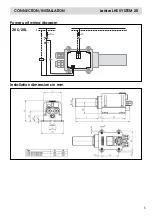
CONNECTION/INSTALLATION

Leister LHS SYSTEM 60

7

Installation dimensions in mm

F2

Fuse

L1
N

K1

L2

L3

PE

L3

L2

L1

P
N

F1

Max 10A

K1

K1

S2

S1

OFF

ON

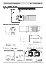
Power unit wiring diagram

60S / 60L

Control unit wiring diagram

20S / 20L, 40S / 40L, 60S / 60L

Summary of Contents for LHS

Page 1: ...sening solvent free adhesives and melt adhesives Sterilizing packaging materials such as bottles corks and containers Separating and fusing synthethic fibres and fabrics Soldering processes on thin metal parts Speeding up mixing processes and dissolving foams which can arise during mixing and filling operations Welding thermoplastic materials Removing plastic mould flash Putting a shine on plastic...

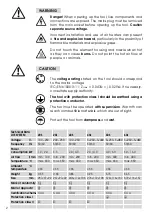
Page 2: ... up the tool live components and connections are exposed The mains plug must be removed from the main socket before opening up the tool Caution separate source voltage Incorrect installation and use of air heaters can present a fire and explosion hazard particularly in the proximity of flammable materials and explosive gases Do not touch the element housing and nozzle when hot as they can cause bu...

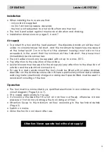
Page 3: ...y attention to the direction of the airflow Leister blowers must be used for the air supply pay attention to the direction of rotation and the electrical connection For use in a dusty environment the tool should be fitted with a Leister stainless steel filter on the air intake connection Where a particularly critical dust problem exists eg metal electrically charged or damp dust special filters mu...

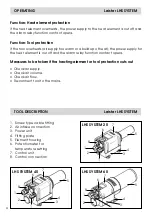
Page 4: ...the power supply for the heat element is cut off and the alarm relay function contact opens Measures to be taken if the heating element or tool protection cuts out Check air supply Check air volume Check air flow Re connect tool to the mains 6 5 2 1 1 4 7 8 3 5 2 1 4 5 2 1 4 3 LHS SYSTEM 20 LHS SYSTEM 40 LHS SYSTEM 60 1 Screw type cable fitting 2 Air intake connection 3 Power unit 4 Fitting plate ...

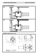
Page 5: ...5 CONNECTION INSTALLATION Leister LHS SYSTEM 20 Installation dimensions in mm F2 Fuse P N F1 Max 10A L N N L1 K1 K1 K1 S2 S1 OFF ON Power unit wiring diagram 20S 20L ...

Page 6: ...TALLATION Leister LHS SYSTEM 40 6 Installation dimensions in mm F2 Fuse L1 N K1 L3 L2 L1 L2 L3 P N F1 Max 10A K1 K1 S2 S1 OFF ON N L1 F2 Fuse L N K1 P N F1 Max 10A K1 K1 S2 S1 OFF ON Power unit wiring diagram 40S 40L ...

Page 7: ...INSTALLATION Leister LHS SYSTEM 60 7 Installation dimensions in mm F2 Fuse L1 N K1 L2 L3 PE L3 L2 L1 P N F1 Max 10A K1 K1 S2 S1 OFF ON Power unit wiring diagram 60S 60L Control unit wiring diagram 20S 20L 40S 40L 60S 60L ...

Page 8: ...rantee a correct and reliable repair service within 24 hours using original spare parts in accordance with the circuit diagrams and spare parts lists Guarantee and liability are in accordance with the guarantee certificate as well as with the currently valid general business and sales conditions Leister Process Technologies rejects any guarantee claims for tools which are not in their original con...

Reviews: