background image

78

8. Operation

8.2.4 Polarization (TL)

• Use the 

TL/IL

  function button to switch to

transmitted light (TL).

• Select the 

POL 

(polarization) contrast method

by pressing the variable button 

POL

.

Alternatively: press the variable button

CHANGE TL 


.

(For details on button assignments, please see
the identification sheet.)

POL

 will appear on the LeicaScreen.

Manual Method:

• Move the polarizer on the condenser into the

beam path.

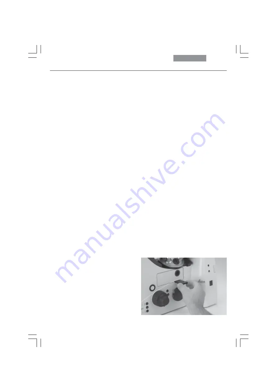
• Insert the analyzer into the right side of the

stand until it clicks into position (Fig. 110).

• Bring the polarizer and analyzer into cross

position until they reach maximum darkness.

• Place a specimen on the stage and select a

suitable objective.

Motorized Method:

• If the microscope is equipped with the rel-

evant components, the polarizer will be acti-
vated automatically in the condenser when
the 

POL 

contrast method is selected. The ana-

lyzer cube is also automatically positioned in
the beam path.

Combined Methods:

• The Leica DMI6000 B microscope permits

purely mechanical and motorized components
— such as a mechanical analyzer and motor-
ized polarizer — to be combined.

Fig. 110

Inserting the analyzer

Summary of Contents for DMI6000 B

Page 1: ...1 Leica DMI6000 B Operating Manual...

Page 2: ...tzlar Germany Responsible for contents Bernard Kleine Marketing CM Compound Microscopy Product Manage ment Holger Grasse Safety Officer according to MPG 30 In case of questions please contact the hotl...

Page 3: ...3 Leica DMI6000 B Operating Manual...

Page 4: ...d trademark of Microsoft Corpora tion The names of companies and products used herein may be trademarks of their respec tive owners The instructions contained in the following doc umentation reflect s...

Page 5: ...ast Rings 69 7 8 Setting the Motorized Polarizer 70 7 9 Adjusting the Light Sources 71 Contents 1 Important Notes about this Manual 7 2 Intended Purpose of the Microscope 8 3 Safety Notes 9 3 1 Genera...

Page 6: ...81 8 5 Focusing 82 8 6 Tubes 84 8 7 Eyepieces 85 8 8 Objectives 85 8 9 Stages and Object Displacement 88 8 10 Magnification Changer 89 8 11 Light Sources 89 8 12 Aperture and Field Diaphragm 90 9 Trou...

Page 7: ...rated incorrectly Explanatory note Item not contained in all configurations Text symbols pictograms and their meanings Caution This operating manual is an essential com ponent of the microscope and mu...

Page 8: ...y and easily Variable illumination and imaging beam paths as well as HCS optics modular accessories and a comprehensive range of peripherals complement the Leica DMI 6000 B inverted research stand The...

Page 9: ...on the user must follow the instructions and warnings contained in this operating manual Caution The devices and accessories described in this operating manual have been tested for safety and potentia...

Page 10: ...placements other than those of the types and the current rat ings listed here Using patched fuses or bridging the fuse holder is not permitted The use of incorrect fuses may result in a fire hazard 90...

Page 11: ...ion Protect the microscope from excessive tem perature fluctuations Such fluctuations can lead to the accumulation of condensation which can damage the electrical and optical components Ambient temper...

Page 12: ...ication Aautomatic Illumination Manager aperture field diaphragm intensity process switching Automatic color neutral intensity control Motorized shutter switching speed 50ms Lamp housing mount for up...

Page 13: ...mm Fixed micromanipulation stages Ceramic coated stage plate 248mm x 204 122mm Heated stage plate from 3 C above room temperature to 60 C 248mm x 204 122mm Temperature controlled stage plate 0 C to 60...

Page 14: ...8 0 55 Condenser heads can be swung out Condenser S70 with additional lens for low magnifications All condensers suitable for magnifications from 1 25x to 100x With or without motorized or manual pola...

Page 15: ...and ports SmartMove ergonomic controller for x y z and 4 additional vari able function buttons Separate control unit for all motorized and electronic elements of the microscope such as Objective turre...

Page 16: ...video port A switchable mirror diverts either 100 of the light to the eyepieces or camera port or splits it with 50 each going to the eyepieces and camera port A Bertrand lens is also available as an...

Page 17: ...llumination unit consists of an illumination carrier and the transmitted light illumination column The transmitted light illumi nation carrier does not contain a lamp housing but a filter module for t...

Page 18: ...caScreen 6 Light intensity 7 Field diaphragm 8 TL IL switching 9 Aperture diaphragm 10 Focus wheel 11 Variable function buttons 12 Right side port 13 Booster lens 14 Lamp mount 15 Condenser head 16 Co...

Page 19: ...l buttons 2 Focus wheel 3 Variable function buttons 4 Opener for drawer 5 Drawer 6 Right side port 7 Analyzer slot 8 Centering window 9 Field diaphragm centering 10 Incident light lamp housing 11 Obje...

Page 20: ...4 Overview of the Instrument Fig 3 Leica DMI 6000 B front view 1 LeicaScreen 2 Front control panel 3 Port switching 4 Top port 5 Manual transmitted light filters 6 Field diaphragm centering 1 2 3 4 6...

Page 21: ...g 4 Overall view of Leica DMI 6000 B with SmartMove remote control module Fig 3b SmartMove remote control module 1 Travel in x 2 Travel in y 3 Focus 4 Variable function buttons preassigned at factory...

Page 22: ...uite LAS software package Instructions and list of microscope presets identification sheet The system package contains the microscope s accessories Eyepieces Objectives Condenser Lamp housings with ac...

Page 23: ...leather or linen cloth Even small traces of finger perspiration can damage the surfaces in a short time See the chapter Care of the Microscope p 95 for additional instructions Caution Do not connect...

Page 24: ...damage from vibra tions the following components should be dis assembled and packaged separately Unscrew the objectives Remove the eyepieces Remove the condenser Remove the specimen stage Remove the...

Page 25: ...hen using intermediate systems and optical accessories the sequence may vary In this case read Chapter 6 15 Optional Accessories p 52 6 1 Assembly Tools If possible the microscope should be assem bled...

Page 26: ...upright and fasten it with the 4 screws When fastening the transmitted light illumina tion carrier do not hold it so as to ensure its op timal alignment with the optical axis The tilt angle of the il...

Page 27: ...llows when making changes to the IC prism disk Remove the front cover Fig 11 below the objective revolver after releasing the socket screws Fig 10a Insert the DIC prism disk Fig 10b in its receptacle...

Page 28: ...gular manual 3 plate cross stage position ing range 83mm x 127mm Manual micromanipulation 3 plate cross stage positioning range 40mm x 40mm Motorized micromanipulation 3 plate cross stage positioning...

Page 29: ...use the shorter of the three screws in the front hole and the equally long ones in the rear holes Use a clean cloth to remove dust and packing material residue from the stand s contact surface with t...

Page 30: ...ewdriver Retighten these screws from time to time after frequent use The attachable mechanical stage has been pre adjusted in the factory In the event that the at tachable mechanical stage runs out of...

Page 31: ...mechanical stage The insert frames Fig 20a to c differ at this point These are held by two screws on the at tachable mechanical stage and changed by re leasing the screws Fig 21 Inserts for fixed sta...

Page 32: ...ect the Y cable as follows In sert the small round plug into the COAX CTRL socket and the second flat plug in the XYZ Con trol socket of the CRT6000 box Connect the plug with the two cables to the Sma...

Page 33: ...e Acti vate the Bertrand lens and focus or use a fo cusing telescope Fig 32 Move the stage until the bright circle is in the middle of the field of view Next tighten the stage swing the Ber trand lens...

Page 34: ...e the light rings start by removing the complete condenser from the transmitted light illumination axis Simply re lease the socket head screw at the right side of the condenser mount The condenser can...

Page 35: ...ing is lying flat in the holder of the tool Press the cheeks of the tool to grasp the light ring Place the light ring in the desired opening and make a note of the opening and light ring designation f...

Page 36: ...with guide grooves Select a position and make sure that the two mounting screws have been released to the point that they no longer extend into the position It is advisable to remove one of the screw...

Page 37: ...f the disk Use only the left centering screw to position the prism see ICT operation The right centering screw must not restrict the range of adjustment under any circumstances If necessary carefully...

Page 38: ...dry 3 S23 0 53 4 S28 0 55 Condensers 3 and 4 are screwed directly into the condenser body A spacer ring 42 2 must be screwed into the thread at the bottom of the condenser body prior to installing con...

Page 39: ...e objective turret disk are num bered Fig 45 Depending on your equipment the individual objectives have already been assigned to specific positions at the factory For details on the exact positions of...

Page 40: ...ng the Transmitted Light Lamp Housing Place the lamp housing in the transmitted light lamp housing mount fig 47 and fasten it with the clamping screw on the side Thread the cable through the transmitt...

Page 41: ...n IR radiation Therefore lamps have to be operated in closed housings Remove the fastener screw on the housing Fig 50a Lift the housing off Fig 50b Remove the lamp Caution Do not remove the new lamp s...

Page 42: ...crews Fig 54 Lamp housing 106z 1 Collector adjustment 2 Vertical lamp adjustment 3 Horizontal lamp adjustment 4 Adapter ring Fig 53 Lamp housing mount 1 2 2 Fig 52 Leica DMI 6000 B rear panel 1 Instal...

Page 43: ...several positions 1 Slide pulled out no effect 2 Filter position wavelength of the installed filter acti vated 3 Depending on orientation of slide a symbol visible center orientation The intensity of...

Page 44: ...e protection Fig 58 risk of explosion Never touch the glass parts of the burner with bare hands Never look directly into the beam path blinding hazard Lamp Housing 106 z This lamp housing is suitable...

Page 45: ...these supply units The following gas discharge lamps may be used and require different supply units and lamp mounts Fig 60 61 Type Typical Bulb Life 100W high pressure mercury burner direct current 2...

Page 46: ...pull it out of the socket 63 9 Flip the cover up 63 1 Loosen the mounting screws 63 8 on the lamp socket and pull the socket out Remove the transport anchorage red plastic rod in place of the burner i...

Page 47: ...ctions When closing the lamp housing make sure that the pins of the contact plug engage in their sockets 63 9 Tighten the screws of the cover and press the contact plug home Place the lamp housing in...

Page 48: ...ged then automatically turns to the outside and you can be sure that the cube is positioned in the correct holder You can therefore postpone installing the filter cubes un til after the microscope has...

Page 49: ...oyed or block the disk For the next cube close the drawer to the point that the disk is once again free to turn Once you have reached the next position open the drawer fully once again Continue in thi...

Page 50: ...triple position holder to the top of the manual con denser The holder has a guide that must be in serted in the opening next to the screw threads The holder must be positioned so that the polar izer...

Page 51: ...alyzer for Incident Light and Transmitted Light Remove the cap Fig 72 on the right side of the stand under the fluorescence drawer Insert the analyzer into the receptacle until it latches in place Fig...

Page 52: ...nt run a teach in via the Leica Application Suite LAS software Connecting multiple cameras Two or more cameras for example a digital and an analog camera can be adapted as required When using a DC typ...

Page 53: ...er cable of stand 8 DL reset button 7 1 2 3 4 5 8 6 1 2 3 7 6 5 4 Note The CTR6000 electronics box must not be used with other stands The serial number of the associ ated stand has been recorded on th...

Page 54: ...devices The devices in question must therefore always be disabled before using the Leica Application Suite LAS software Please use the included serial cable Connect the COM1 port of your PC with the R...

Page 55: ...stments overwrite the previous settings The current setting is stored and is retained from one session to the next when power is switched off 2 Controls SmartMove knobs for stage and focus control Fix...

Page 56: ...on the left side of the stand Switch on the power for the stand Hold the buttons until the initialization is complete The standard information display will now appear in the LeicaScreen Fig 81 and 82...

Page 57: ...axis Change to objective Teach in parfocality Change operating mode dry imm Illumination Manager Magnification Changer Focusing 1 Set stops Go to stop Change step increment coarse fine XY stage posit...

Page 58: ...er cube CUBE 1 6 Select filter cube in position 1 6 CHANGE CUBE CW Change cube clockwise 1 4 CHANGE CUBE CCW Change cube counterclockwise 4 1 INT FLUO Increase intensity fluorescence INT FLUO Reduce i...

Page 59: ...tly the LeicaScreen will display an error message See Troubleshooting chapter p 91 Components such as diaphragms condensers light and phase contrast rings have been pre centered at the factory It may...

Page 60: ...ine 2 Objective magnification Line 3 Illumination diaphragms Line 4 Active ports Line 5 Focus stops The content of the display changes according to the active function Contrast Method Objective Magnif...

Page 61: ...buttons The vari able function buttons have different functions depending on the features of the individual mi croscope Fixed Function Buttons on the Left Side The TL IL button 84 1 toggles between th...

Page 62: ...ont Panel Fig 87 Fig 85 Function buttons left side of stand 1 Variable function buttons 2 Open close aperture diaphragm 3 TL IL switching 4 Open close field diaphragm 5 Increase decrease light intensi...

Page 63: ...ntrol panel 1 100 light to eyepiece 2 Toggle ports 3 Shutter 4 Switch magnifications 5 Magnification 1x 6 Selecting filter cubes Fig 88 1 Focus control buttons 2 Open filter drawer CUBE The CUBE 1 to...

Page 64: ...Control Module SmartMove Knobs Use the knobs 89 1 and 89 2 to move the stage in X and Y directions Knob 89 3 focuses the image The height of the knobs can be adjusted to a comfortable working positio...

Page 65: ...dependent on the thickness of the specimen and may require adjustment for each new specimen Koehler Illumination Suitable aperture and field diaphragm values have been preset for each objective The c...

Page 66: ...er ring is just covered You should see light when looking through the eyepieces at this point If the light is too bright reduce it as required Remove all unneeded components from the light path Swing...

Page 67: ...d look directly into the tube Your eye should be around 10 to 20 cm from the tube Change the size of the aperture diaphragm until its image is clearly visible in the pupil of the objective Set the ape...

Page 68: ...a specimen on the stage Focus the specimen using the SmartMove or the focus wheels Adjust the light intensity with the INT buttons 84 3 Adjusting the Field Diaphragm Close the field diaphragm with th...

Page 69: ...he variable function buttons on the stand Instead of an eyepiece place a focusing telescope Fig 93 in the observation tube or activate the Bertrand lens pull rod 94 1 on tube PH LR Fig 95 Phase contra...

Page 70: ...he objective is congruent with the slightly narrower bright ring light ring in condenser 95 c Caution The centering keys must be removed from the centering openings before changing ob jectives They ma...

Page 71: ...Housing 106 z When a supply unit is used it is turned on first Activate the incident light axis with the TL IL function button FLUO will appear on the LeicaScreen Insert the lamp adjustment reflector...

Page 72: ...p housing 106 z L 1 Lamp adjustment vertical 2 Vertical reflector adjustment 3 Focusing the reflector image 4 Horizontal reflector adjustment 5 Lamp adjustment horizontal 6 Collector focusing 7 Screw...

Page 73: ...cted onto each other as this results in a danger of explosion by over heating Caution The structure of the arc can no longer be made out clearly in lamps that have been in service for a long time The...

Page 74: ...then the computer All motorized microscope components will then run through an initialization phase Note In the case of faulty initialization Init Error message on LeicaScreen see Troubleshooting chap...

Page 75: ...rogramming With the stand switched off press the top three variable function buttons on the left side of the stand Switch on the power for the stand Hold the buttons until the initialization is comple...

Page 76: ...mitted light TL Select the BF brightfield contrast method by pressing the variable button BF Alternatively press the variable button CHANGE TL For details on button assignments please see the identifi...

Page 77: ...ting the phase contrast method the aperture diaphragm is opened fully and cannot be adjusted 8 2 3 Darkfield TL Use the TL IL function button to switch to transmitted light TL Select the DF darkfield...

Page 78: ...the stand until it clicks into position Fig 110 Bring the polarizer and analyzer into cross position until they reach maximum darkness Place a specimen on the stage and select a suitable objective Mot...

Page 79: ...o positioned automatically Place a DIC specimen on the stage Rotate an appropriate objective into place Focus the image with the knob on the SmartMove or the focusing wheel and adjust the intensity wi...

Page 80: ...tware Focus the image with the knob on the SmartMove or the focusing wheel and adjust the intensity with the INT function buttons Options The intensity of the fluorescence can be increased by using th...

Page 81: ...nges accordingly Place a specimen on the stage and select a suitable objective Select the desired filter cube using the fixed function buttons on the front panel The illumination settings for the fluo...

Page 82: ...e objectives Setting Stops Set the lower focus stop by pressing and holding the SET button and pressing the Z button as well The display will show Pressing the button combination again will de lete th...

Page 83: ...and Z but tons hold the button until the stop has been reached Setting the Step Increments It is possible to toggle between Fine and Coarse step increments The Fine value varies to suit the current ob...

Page 84: ...lens Light distribution via Manual control bar Selecting Ports The button on the front control panel switches 100 of the light to the eyepieces Use the button also on the front control panel to selec...

Page 85: ...Note We recommend running a teach in via the Leica Application Suite LAS software when using eyepieces not included in the scope of delivery This will ensure that the total magnification shown in the...

Page 86: ...by pressing the appropriate button Change operating mode via Variable function buttons on stand and SmartMove Leica Application Suite LAS Software OIL only use optical immersion oil according to DIN...

Page 87: ...and Object Displacement Object Displacement Using SmartMove Color Coding of Objectives The magnification of each objective is indicated by a color ring in accordance with DIN ISO stan dards Immersion...

Page 88: ...eed is the same for all objectives The Precise speed varies to suit the current ob jective Switch between Precise and Fast via Variable function buttons on stand and SmartMove Leica Application Suite...

Page 89: ...dent light IL axis For TL and IL The setting can be made in coarse and fine steps Pressing both INT 118 2 buttons as the same time toggles between coarse and fine adjustment The light intensity displa...

Page 90: ...tons are assigned to the currently active transmitted light TL or incident light IL axis Caution The old values will be overwritten by the current ones Caution When using PH or DF the aperture diaphra...

Page 91: ...ections Inform Service and have the supply unit fuse checked Open the shutter p 63 Check the connections of the lamp housings on the microscope transmitted light fluorescence Make sure that the lamps...

Page 92: ...hat it suits the indication on the objective Make sure that you are using an objective with coverslip correction Adjust the correction ring on the objective if present Be sure that a DF objective is b...

Page 93: ...y reach maximum darkness without specimen p 78 The specimen is too thick or too thin Embedding medium or specimen are of birefringent material Rotate the specimen The difference in the refractive indi...

Page 94: ...er p 63 Select the incident light axis IL p 61 Check the antigen antibody combination Insert a new lamp p 44ff Insert the booster p 80 Center the lamp p 71ff Insert a new lamp p 44ff Check the cable c...

Page 95: ...ation water may occur 10 2 Cleaning Caution Residual fiber and dust can create unwanted background fluorescence Cleaning Coated Parts Dust and loose dirt particles can be removed with a soft brush or...

Page 96: ...a subsidiary for repair We also advise against cleaning the inside surfaces of the eyepieces The front lenses of objectives are cleaned as described under Cleaning Glass Surfaces The upper lens is cle...

Page 97: ...unused objective DIC disk opening 11 090 144 020 088 Cover for DIC microscope stand Dust and light protection cover for analyzer slot 11 020 437 101 013 Analyzer slot cover microscope stand Dust and l...

Page 98: ...ion plate was developed to raise the viewing height by 20mm or to raise the side camera ports for oversize cameras or spin ning disks or to use the microscope with an in active bottom port on workbenc...

Page 99: ...epiece Focus Lower focus stop not set Lower focus stop set Focus position not set Focus position set Shutter open Shutter closed Transmitted light filter Field diaphragm rectangular Field diaphragm ro...

Page 100: ...d incident transmitted light DIC Differential Interference Contrast FD Field diaphragm FLUO Fluorescence axis incident light ICR Interference contrast incident light ICT Interference contrast transmit...

Page 101: ...14 34 37 Consumable parts 97 Contrast methods 12 60 76 Contrast settings 67 Controls 15 55 Correction for vision problems 85 Corrective mount 87 CUBE 63 80 Dark field TL 77 92 Diaphragms 60 DIC modul...

Page 102: ...0 15 17 53 59 74 LeicaScreen 18 LeicaScreen 20 56 59 60 75 94 Light intensity 18 61 Light rings 34 59 Light source adjustment 71 Light sources 89 Load 49 64 Lower stop 63 82 Magnification 60 Magnifica...

Page 103: ...nipulation stage 28 TL IL switching 18 Toggling transmitted light incident light 61 Top port 18 20 Transmitted illumination 81 Transmitted illumination unit 17 Transmitted light 65 Transmitted light i...

Reviews: