background image


7


_________________________________________________________________________________________                                                     


2. GENERAL INFORMATION 


LEGUAN  125M1

  is  a  self  propelled  Mobile  Elevating  Work  Platform 

–  or  commonly 

called  access  platform,  designed  for  indoor  and  outdoor  use.  An  access  platform  is 
destined  for  lifting  of  persons  and  their  equipment  only.  It  is  not  allowed  to  use  an 
access platform as a crane.  

LEGUAN 125M1 

 access platform has two nominal loads and two working areas. With 

max. 135 kg load on the platform the machine can be operated over the whole working 
area.  If    the  load  on  the  platform  exceeds  135  kg,  the  working  area  is restricted up to 
max. 200 kg load on the platform. ’ 

LEGUAN

  is  designed  and  built  in  accordance  with  the  international  safety  standards 

and MEWP (Mobile Elevating Work Platform) standars.  
 
The picture below shows the main parts of this access platform:  
1.  Chassis 
2.  Transmission, either with 

wheels or with crawler tracks 

3.  Outrigger 
4.  Outrigger cylinder 
5.  Transport support 
6.  Electric motor 
7.  Connection box of control 

system with emergency 
lowering buttons 

8.  Pedestal 
9.  Valve box at ground level 

10. Lower boom cylinder 
11. Lower boom 
12. Self levelling bar 
13. Linkage piece 
14. Upper boom cylinder 
15. Telescoping cylinder 
16. Upper boom 
17. Telescopic boom 
18. Platform 
19. Controls box at platform 
20. Valve, release of slewing 


5

3

4

1

6

2

7

8

9

10

11

12

13

14

15

16

17

18

19

20


Summary of Contents for 125

Page 1: ...Operators and Service Manual 2014 Version 6 2015 27 8 2015 ...

Page 2: ...level and releasing of slewing 16 6 2 4 230V connection and switches 17 6 2 5 Lower controls Option 17 7 STARTING THE ENGINE ELECTRIC MOTOR 18 8 DRIVE CONTROL 19 8 1 DEFINING THE GRADIENT OF THE SLOPE 20 9 OPERATION OF THE OUTRIGGERS 22 10 OPERATION OF THE BOOMS 23 11 EMERGENCY LOWERING 24 12 ENDING THE OPERATION 24 13 TRANSPORTING INSTRUCTIONS 25 14 SERVICE MAINTENANCE AND INSPECTION INSTRUCTIONS...

Page 3: ...3 _________________________________________________________________________________________ 18 TROUBLESHOOTING 36 18 SERVICE HISTORY 39 Attachments Hydraulic schematic Electric schematic ...

Page 4: ...nt any damages which are the result of using the access platform It is not possible to give explicite operating instructions to all operating conditions of the machine Therefore the manufacturer is not responsible for any damage caused by eventual faults in this Operators Manual The manufacture does not accept any responsibility for consequential losses resulting from the use of this self propelle...

Page 5: ...cident natural disaster damages caused by external mechanical or chemical reasons paint damages especially caused by stone chips air and environmental pollution and strong cleaning agents eventual visible patterns or unevenness of painted surfaces warranty claims that haven t been sent to the manufacturer within 14 days from the date the buyer has noticed the defect In all conditions the buyer sha...

Page 6: ...irektiivi 3 Sähkömagneettista yhteensopi vuutta koskeva direktiivi Machinery Directive Low Voltage Directive Electromagnetic compatibility 2006 42 EC 2006 95 EEC 2004 108 EEC KONEEN SUUNNITTELUSSA ON LISÄKSI KÄYTETTY SEURAAVIA TEKNISIÄ ERITELMIÄ FOLLOWING TECHNICAL SPECIFICATIONS ARE USED WHEN THE MACHINERY WAS DESIGNED Yhdenmukaistetut standardit Harmonized Standards EN280 A2 Ilmoitettu laitos No...

Page 7: ...35 kg the working area is restricted up to max 200 kg load on the platform LEGUAN is designed and built in accordance with the international safety standards and MEWP Mobile Elevating Work Platform standars The picture below shows the main parts of this access platform 1 Chassis 2 Transmission either with wheels or with crawler tracks 3 Outrigger 4 Outrigger cylinder 5 Transport support 6 Electric...

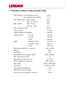
Page 8: ...ength without platform 4500 mm Transport height 23 tyres 1840 mm 20 tyres 1800 mm Tracks 1840 mm Width 23x8 50 12 tyres 1020 mm 20x8 00 10 tyres 999 mm Tracks 1281 mm Platform dimensions W x L 2 persons 1200 x 700 mm Slewing 360º Gradeability 35 Support dimensions outrigger spread 2938 x 2892 mm Max unevenness of set up 2º Max gradient of slope for set up 22 13º Weight depending on equipment 1500 ...

Page 9: ...9 _________________________________________________________________________________________ ...

Page 10: ...10 _________________________________________________________________________________________ 3 1 Reach diagram ...

Page 11: ...3 Max horizontal force and wind speed 4 General user instructions 5 Daily inspection 6 Always use outriggers 7 Symbol stickers pictograms of controls 8 Emergency lowering 9 Residual current device 10 Voltage of electric motor 11 Max support force 12 Distance from energized electric wires 13 Tie down points 14 Tyre pressure 15 LEGUAN 125 sticker 1 2 9 4 3 12 7 8 5 6 10 11 13 8 8 14 15 ...

Page 12: ...ROPERLY CONNECTED TO THE PLATFORM 5 1 Before starting operation All warnings and labels must be read carefully Only persons with min 18 years of age are allowed to use the access platform They must have received sufficient operating instrucions Operator must know all the functions of this access platform as well as the Safe Working Load loading instructions and safety instructions If there is heav...

Page 13: ... lifting of the max allowed number of persons and additional load only Check and make sure that all tyres are in good condition If the tyres are air filled make sure that there is correct pressure in the tyres In order to ensure the safe operation of this access platform the manufacturer has conducted approved tests for the LEGUAN 125 in accordance with the standard EN280 A2 static stability test ...

Page 14: ...rances to voltage carrying electric lines are shown in the following table These clearances must be respected VOLTAGE MIN DISTANCE 0 1000V 2 m 1 45 kV 3 m 110 kV 5 m 220 kV 5 m 400 kV 5 m 5 6 Explosion fire hazard It is not allowed to start the motor engine in a place where one can smell LPG petrol solvent or other flammable substance Do not fill with fuel when the engine is running Charge the bat...

Page 15: ...unction selector switch Drive Outrigger operation Boom operation 3 EMERGENCY STOP switch 4 Drive speed area selector switch 5 Selector switch of propelling electric motor or combustion engine 6 Emergency lowering upper boom 7 Overload control indicator 8 Indicator of working area when the light is on SWL is under 135 kg 9 Choke 10 Emergency lowering lower boom 11 Control lever lower boom 12 Contro...

Page 16: ...OT switch off the main current when the booms are not in transport position The battery charger charges the battery even if the disconnet switch is switched off 6 2 2 Controls on the control valve box at ground level 1 Control levers drive 2 Water level 3 Hour meter 4 Outrigger pressure indicators red LEDs 5 Boom lifting indicator and max support force 9kN 6 Control levers outriggers 6 2 3 Emergen...

Page 17: ...s Option 1 Selector key switch of lower upper controls 2 Ignition switch Stop ON Start 3 Overload control indicator 4 EMERGENCY STOP switch 5 Control lever lower boom 6 Control lever upper boom 7 Control lever slewing 8 Control lever telescoping boom Function of lower controls 1 Ignition switch at platform must be turned to ON position 2 Select with the selector key switch no 1 either lower contro...

Page 18: ...the 230V cable and check also function of residual current device With the TEST button you can also check that there comes 230V to the machine 3 Make sure that the booms are down in transport position If necessary press on the emergency lowering buttons one by one 4 Check emergency stop switch release by turning the switch if it is switched on 5 Fasten safety harnesses on the fastening points at p...

Page 19: ...rive control valve see page 15 By pushing the left lever left side wheels turn forward by pulling the lever left side wheels turn backward Right side wheels turn in the same manner by pushing and pulling the right side lever 4 Turning of the machine is based on the skid steer principle When you want to turn the machine either to the right or to the left push pull the drive control lever on the inn...

Page 20: ...taken into account with an access platform on tracks In order to secure the maximum life expectancy for the rubber tracks and crawler track chassis follow the instructions below The lifespan of the track system of an access platform on rubber tracks is heavily dependent on the working environment and the way of working The operator can increase the lifespan by following the below mentioned operati...

Page 21: ...he rubber track the tracks must be flushed with water immediately after ending operation 8 2 2 Operating instructions Check track tension regularly Too loose tension can make tracks jump off the sprockets Do not over tension the tracks because this causes big power loss and excessive wear on the sprockets and tracks Change turning direction as often as possible Turning continuously only in one dir...

Page 22: ... 4 Drive the outriggers down on the ground firmly enough They must be driven down so much that all wheels lift off the ground Usually it is not necessary to push the outriggers further unless it is necessary to reach higher Make sure that the wheels do not touch the ground before starting to lift the booms 5 When all outriggers are firmly on the ground and wheels lifted off the ground check the ho...

Page 23: ... the indicator and the system must me checked 6 LEGUAN 125 is also equipped with an overload control system which prevents boom movements in case the 200 kg safe working load is exceeded or in case the telescopic boom comes out more than allowed when load on the platform is over 135 kg Should this happen there is an audible warning signal and an indicator lights up at the control panel The booms c...

Page 24: ...ned and going straight down to transport supports If necessary the booms can be rotated by opening the release valve of the slewing cylinder see 6 2 3 and then pushing the booms to desired position Switch off main current before rotating the booms Always check function of emergency lowering before starting operation 12 ENDING THE OPERATION When ending operation 1 Lower the booms down to transport ...

Page 25: ...s are mounted in order that the outriggers will not get damaged There is an automatic hydraulic brake in the rear axle which engages automatically when the engine motor is not running If the machine is transported on a trailer or on a lorry or similar vehicle it must be tied down properly There are four tie down points marked on the corners of the chassis which make it easy to tie down the machine...

Page 26: ... etc components Risk of serious injury Make sure that services are made in accordance with this Operators Manual and with the Service Manual of the engine manufacturer Stop the engine before starting any service or inspection operation DISCONNECT ALSO THE 230V MAINS CURRENT Do not smoke during service and inspection operations Keep the machine and especially the platform clean Make sure that the o...

Page 27: ...ely if hydraulic fluid penetrates your skin Wash carefully with water and soap any body part that has come in contact with hydraulic oil Hydraulic oil is also harmful to the environment prevent oil leakages Only use hydraulic oil type approved by the manufacturer Never handle pressurized hydraulic components because in case of failure of a fitting or component ejection of high pressure hydraulic f...

Page 28: ...ic pressure adjustments FCH CH Function of control valves F CH Mounting of booms on the chassis CH Condition of steel construction CH Movement speeds of booms F CH A Greasing of the machine R Function of load control system F CH A Level position of water level F CH Hydraulic oil type Statoil Hydraulic Oil 131 45 65 C Vickers 104 C IP 2 81 80 FSD 8401 Hydraulic system oil volume oil tank 35 l compl...

Page 29: ...lic oil tank no 2 on the chassis Replace the filter by removing the filter cap and replacing the filter cartridge When changing hydraulic oil the oil can be removed with a suction pump from the opening of breather cap no 3 or by opening the drain plug In both cases it is important to clean the magnetic drain plug Hydraulic pressure filter cartridge no 4 must be changed always when return filter is...

Page 30: ...e position of the water level on the control valve box If the positions are different adjust the water level on the valve box with the adjustment screws so that both levels are in the same position Do the adjustment both lengthwise and sideways 15 8 Adjustments in hydraulic system All settings of the hydraulic system have been made at the factory and normally there is no need to adjust them Pictur...

Page 31: ...ing of the booms the electric solenoid valve in the cylinder no 2 opens and oil flows through the adjustable restrictor valve into the tank and the boom s come down Boom lowering speed is adjusted with the restrictor valve Adjustment of lift cylinder emergency lowering is on the side of the oil tank On some cylinders the lowering speed is adjusted with check valves no 3 There are check valves at t...

Page 32: ... cuts off the power movement of telescope is restricted and 135 kg indicator 5 goes out If telescope has been extended and one puts more load than allowed on the platform there is an audible warning signal and the indicator 6 starts to blink In the 135 kg overload situation the safety valve K9 remains currentless preventing operation of booms Overload control system is reset by stopping the engine...

Page 33: ...ly in the right place so that it gives sufficient support to the booms without causing extensive stress on the booms Limit switches that are monitoring the stroke of telescoping cylinder are mounted at the end of upper boom Primary limit switch S16 1 stops telescoping movement if load on platform exceeds 135 kg the movement sensing rail 3 turns the arm of the limit switch If the telescoping moveme...

Page 34: ...ve control levers Check track tension as follows Way 1 Measure the slack between the track rollers and inside of the track no 1 in the picture above The slack should be 10 30 mm If it is more than 30 mm tighten the track Way 2 Check if the front end plate no 4 of the track tightening system can move freely The end plate is located at the front of the track system behind the front idler If the plat...

Page 35: ...r weldings in load carrying parts can be performed only by permission from the manufacturer ATTENTION It is not allowed to change the construction and structure of this access platform without written permission from the manufacturer 17 INSTRUCTIONS FOR TEMPORARY STORAGE The cable of the pole of the battery should be disconnected if the access platform is being stored for a period longer than 1 mo...

Page 36: ...connect switch is in OFF position Petrol engine ignition switch is in OFF position Engine electric motor selector switch at platform is in wrong position Emergency stop switch is pushed down Engine is cold Fuel valve is closed Fuel tank is empty Empty start battery Fuse inside petrol engine ignition switch is broken Fuse inside the connection box is broken The fuses are at the end of the terminal ...

Page 37: ...top button accidentally pushed down Electric motor thermal overload relay F1 in connection box has gone off Connection fault in mains or 12V wiring Lower the booms by using emergency lowering Check that there is current in mains Release emergency stop and restart Wait for approx 2 min and start the motor the relay will return to ON automatically Find out the reason for overload Check voltages and ...

Page 38: ...ve in Air in outrigger cylinder s Dirt in outrigger cylinder check valve Faulty check valve Faulty outrigger cylinder seals Put extra support plates under the outriggers or move to another place Drive outriggers up and down a couple of times Clean valve with compressed air Change valve Change outrigger cylinder seals Platform tilts backwards by itself when booms are down on transport supports Air ...

Page 39: ..._____________________ 3 _______________ _________________ _________________________________ 4 _______________ _________________ _________________________________ 5 _______________ _________________ _________________________________ 6 _______________ _________________ _________________________________ 7 _______________ _________________ _________________________________ 8 _______________ __________...

Reviews: