background image

8

STATUS LEDS

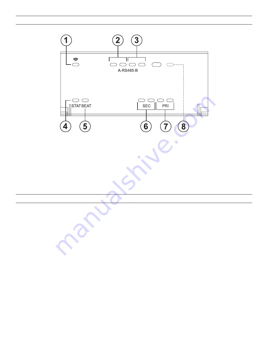
The controller provides a number of status LEDs, with all but one visible with the front access door closed.

1.  WiFi

 (green) - This option is not used

2.  RS485 “A” 

(COM1) - Transmit (TX, Yellow) and Receive (RX, Green)

3.  RS485 “B”

 (COM2) - Trams,to (TX) and Receive (RX)

4.  STAT

 (Green) - Remains lit

5.  BEAT 

(Yellow) - “Heartbeat” LED that blinks at 1Hz during normal operation

6.  Secondary Ethernet

, SEC (LAN2) “link” (Green) and “Activity” (Yellow)

7.  Primary Ethernet

, PRI (LAN1) “Link” (Green), “Activity” (Yellow)

8.  BACKUP 

(Behind door) - Green, typically Off unless a USB drive is inserted, or a backup, restore, or factory recovery image install 

is in progress.

USING STATUS LEDS

The LMJA-8125/8300 includes several LEDs that can help you determine the status of the unit. They are located in two places as 

shown in the Status LEDs diagram above: the top of the LMJA-8xxx (visible through the cover), and for serial ports, on the bottom board 

(visible only with cover removed). From left to right these LEDs include:

•  Status (STATUS)
•  Heartbeat (BEAT)
•  Serial Ports (see USB Ports section on page 10 for explanation)
•  Ethernet Ports (SEC, PRI)

Ethernet Ports

Each Ethernet port (“SEC” for LAN2, “PRI” for LAN1) has one green LED, visible on the top cover. The LED indicates activity on the 

associated port as follows:

• 

Off

 – No Ethernet link is made.

• 

On

 – Ethernet link is present, but no activity on the LAN.

• 

Blinking

 – Ethernet link is present with data activity on the LAN.

Heartbeat

The “BEAT” LED is located to the right of the Ethernet LEDs, and is yellow. Under normal operation, this LED should blink about once 

per second. If the heartbeat LED stays on constantly, does not light, or blinks very fast (more than once per second), contact technical 

support.

Status

When power is applied, the “STATUS” LED is located to the right of the heartbeat (“BEAT”) LED, and is green. This LED provides a CPU 

machine status check, and should be lit when the LMJA-8xxx is powered. 
If the STATUS LED is not lit while power is applied, contact Wattstopper Technical Support.

Summary of Contents for Wattstopper DLM LMJA-8 Series

Page 1: ...and return any damaged components for immediate repair or replacement Included in this Package Included in this package you should find the following items 1 DLM LMJA 8125 8300 controller unit with m...

Page 2: ...ocation that allows clearance for wiring servicing and module removal Environmental Requirements Note the following requirements for the LMJA 8125 8300 controller mounting location This product is int...

Page 3: ...de or the local AHJ requires that low voltage wiring such as control and communication wiring be run inside conduit or where needed for customer specifications See the instructions provided with the L...

Page 4: ...cale Verify all measurements before drilling Tab Mounting Dimensions Measurements shown below are in inches and mm NOTE DIN rail mounting is recommended over tab mounting 1 The LMJA 8125 8300 controll...

Page 5: ...ord w ttstopper Note that both the user name and password are case sensitive Click the Login button Logins with individual permissions can be customized for different users Refer to the Operation Manu...

Page 6: ...for direct connection to the Segment Manager proceed as follows 1 Click on the Start menu and type network sharing center Then Click on Network and Sharing Center in results 2 Click Local Area Connect...

Page 7: ...er the IP address and Subnet mask Set the PC to 192 168 1 xxx where xxx is any number between 001 and 255 and is not the same as the Segment Manager Set the subnet mask to 255 255 255 0 7 Click OK the...

Page 8: ...tom board visible only with cover removed From left to right these LEDs include Status STATUS Heartbeat BEAT Serial Ports see USB Ports section on page 10 for explanation Ethernet Ports SEC PRI Ethern...

Page 9: ...s Off repeating Some scenarios where the BACKUP LED is used include USB Drive Inserted A USB flash drive is inserted in the USB 2 0 port to either backup a commissioned unit to the USB drive or to res...

Page 10: ...iates a controlled shutdown of the controller ensuring that all station data is preserved This provides an alternative to the platform stop station command while connected online with controller WIRIN...

Page 11: ...shown on controller 1 RS485 ports and bias switches 2 Ethernet ports 10 100 Mbit RJ 45 3 Earth ground and 24V power input 4 WLAN is NOT enabled 2 4 1 3 SEC RS485 A COM 1 RS485 B COM 2 END BIA MID ACC...

Page 12: ...150 Ohm termination resistor MID RS485 biasing or termination 47 5K bias resistors with no termination resistor Often adding RS 485 biasing can improve communications by eliminating indeterminate idle...

Page 13: ...ions Wiring Before connecting cables provide strain relief for them to prevent damage to the LMJA 8xxx Connect communications wiring to the LMJA 8xxx see page 11 which include RJ 45 Ethernet for PC or...

Page 14: ...168 1 140 This address can be changed See the Segment Manager 2 4 Operation Manual for details The subnet mask is 255 255 255 0 The factory default IP address for LAN2 on a LMJA 8xxx is 192 168 5 140...

Page 15: ...ATUS LED is located to the right of the heartbeat BEAT LED and is green This LED provides a CPU machine status check and should be lit when the LMJA 8xxx is powered If the STATUS LED is not lit while...

Page 16: ...0 rooms common spaces WIRING EXAMPLES continued EXAMPLE Three story building with no more than 40 rooms common spaces per floor Ethernet cable to LAN PC or BAS Segment Networks 1 2 and 3 LMJA 8xxx LMJ...

Page 17: ...NB Switch NB Routers Power Supply 1st Floor Rooms 141 180 2nd Floor Rooms 201 240 2nd Floor Rooms 241 280 3rd Floor Rooms 301 340 4th Floor Rooms 401 440 LMJA 8xxx 5th Floor Rooms 501 540 Ethernet Dai...

Page 18: ...ith the ability to physically connect a computer to the lighting control network when needed for service or to purchase our Remote Access cellular based service RACCESS OPTION 2 Virtual network isolat...

Page 19: ...ivalency Device equivalency Connected devices With 0 LMFC 011s or LMRCs used for scheduling functions 1 10 Count connected devices With 1 24 LMFC 011s or LMRCs connected 3 20 Count connected devices W...

Page 20: ...ings and Certifications The LMJA 8125 8300 controller has the following agency listings compliances and certifications UL 916 Energy Management Equipment Edition 4 FCC Part 15 Class B Federal Communic...

Page 21: ...ipment for measurement control and laboratory use PASS INITIATING A CONTROLLER SHUTDOWN When locally servicing an installed and configured commissioned unit use this feature before removing power NOTE...

Page 22: ...rofits ou aux co ts d enl vement d installation ou de r installation Wattstopper garantiza que sus productos est n libres de defectos en materiales y mano de obra por un per odo de un 3 a o No existen...

Reviews: