Automatic transfer switch
4 226 81
Installa
tion and user manual
7
2.1
Selection keys
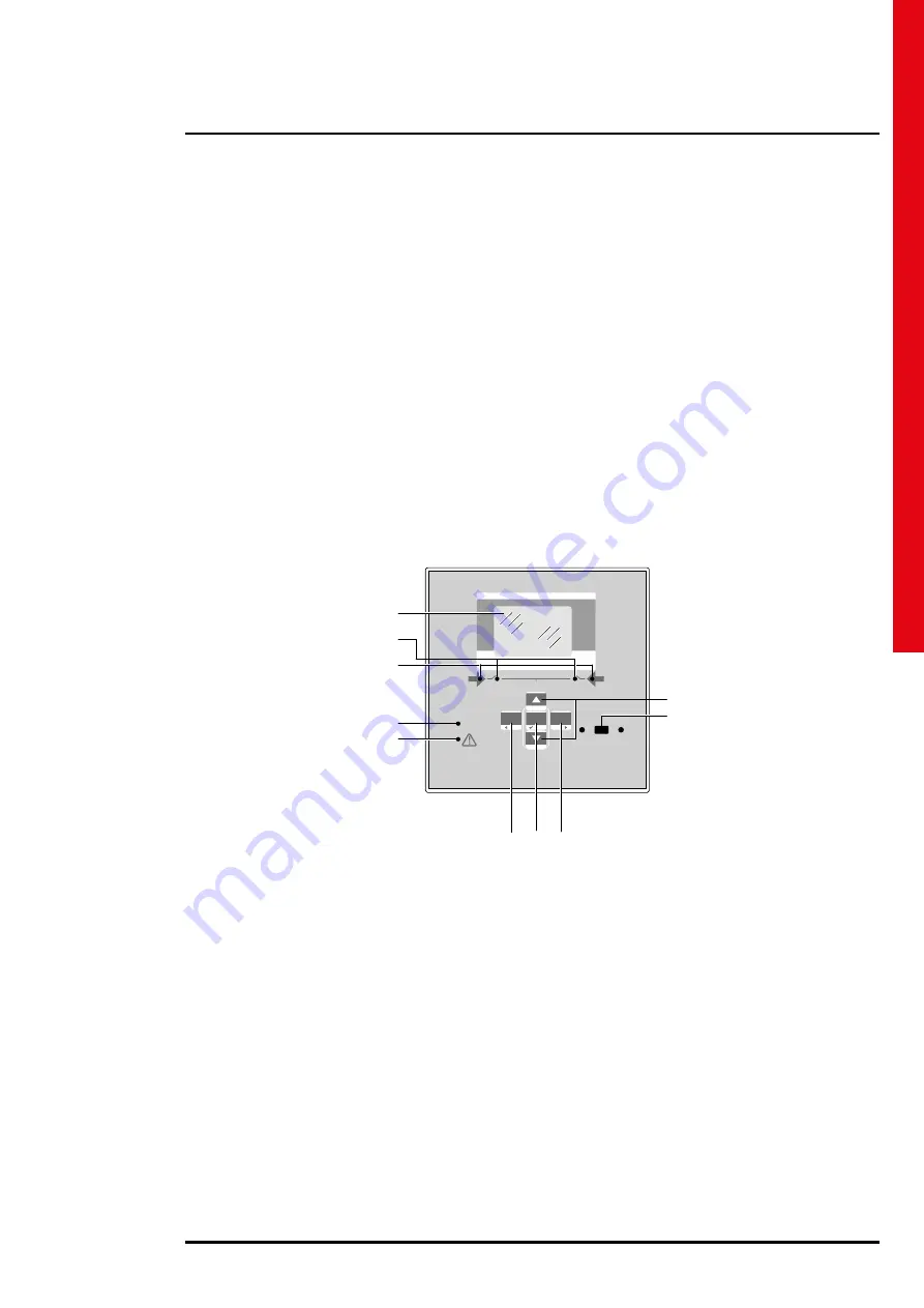
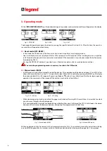
• OFF button (F) – It selects the OFF operating mode.
• AUT button (G) – It selects the automatic mode.
Green AUT LED (D) lights (when selected).
• MAN button (H) – It selects the manual operating mode.
•
•
▲
and
▼
keys (I) - Used to scroll through the display pages or to select the list of options in a menu.
Simultaneously
pressing of
▼
and
▲
recalls up the main menu.
2.2
LEDs
• AUT LED (green) (D) – It indicates the automatic mode active.
• Alarm LED (red) (E) – Flashing, it indicates an active alarm.
• Line 1 voltage status LED (green) (C) – It indicates the line voltage of source 1 S.Q1 is within the programmed limits.
• Line 2 voltage status LED (green) (C) - It indicates the line voltage of source 2 S.Q2 is within the programmed limits.
• Q1 status LED (yellow) (B) - If fixed, it indicates the open or closed state of the devices Q1 source line 1. If flashing, it
indicates a mismatch between the desired state of the breaker and its true state detected by the feedback input.
• Q2 status LED (yellow) (B) - If fixed, it indicates the open or closed state of the device Q2 source line 2 breaker. If flashing,
it indicates a mismatch between the desired state of the breaker and its true state detected by the feedback input.
N.B. If the LED is on, the relative function is activated.
LINE 1
LINE 2
LOAD
IR COM
4 226 82
OFF
_
AUT
MENU
MAN
+
MENU
AUT
OK
RESET
Q1
Q2
IEC 60947-6-1
A
B
C
D
E
I
L
F
G
H
Fig. 1 - Frontal panel
2.3
IR Input
• IR Input (L) – Connecting IR port to connect IR-USB or IR-WiFi dongle accessories. They allow the dialogue between ATS
and SW ACU or APP ACU.
2. ATS front panel description


