14
• The inputs and outputs are identified by a code and a sequence number. Example: the digital inputs are identified by
code INPx, where x is the number of the input. In the same way, digital outputs are identified by code OUTx.
CODE
DESCRIPTION
BASE
INPx
Digital Inputs
1…6
OUTx
Digital outputs
1…7
• Internal variables (bit) are associated to inputs/outputs. For instance, it is possible to apply limit thresholds to the mea-
surements done by the ATS. In this case, an internal variable named LIMx will be activated when the measurements will
go outside the limits defined by the user.
• The following table shows all the I/Os and the internal variables managed by the automatic transfer switch with hi-
ghlighting of their range (variables number per type).
CODE
DESCRIPTION
RANGE
LIMx
Limit thresholds
1…4
REMx
Remote-controlled variables
1…16
UAx
User alarms
1…4
CNTx
Programmable counters
1…4
• Functions associated to the inputs are the 4 described in the above table.
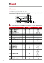
• LIMx: internal variable that identifies a limit value set by the user and managed by the ATS. Its status (active or not)
depends by out-of-limits of one measurement set by the user.
• CNTx: internal counters that can count pulses coming from an external source (through a digital input INPx) or the
times that a certain condition has been verified.
Example: defining a limit threshold LIMx as count source, it will be possible to count how many times one measurement
has exceeded a certain limit.
• REMx: allow the managing of remote variables.
• UAx: allow the activation and managing of 4 programmable alarms.
Function
Upper threshold
Lower threshold
Threshold delay
Status of the limit
variable
Type of measure
Measure value
Fig. 26 - Limit thresholds
8. Communication

