6
1. General features
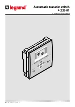
The automatic transfer switch has been designed for switching applications between two power sources (power grids or
generators). ATS has an LCD screen to provide a clear and intuitive user interface.
1.1
Description
• 128x80 pixel, backlit LCD screen with 4 grey levels.
• 5 keys for functions and setting.
• 4 LEDs for plant synoptic (source line and breakers status).
• 2 LEDs for alarm presence and AUTO mode active.
• 5-language text for measurements, settings and messages.
• Programmable I/O functions.
• Fully user-definable alarm properties.
• Line 1: 3-phase + neutral voltage reading input (S.Q1).
• Line 2: 3-phase + neutral voltage reading input (S.Q2).
• 100-240VAC power supply.
• Voltage thresholds with programmable hysteresis.
• Front optical programming interface, galvanically isolated, which can be connected with USB and WiFi dongles.
• 6 programmable digital inputs (negative).
• 6 + 1 outputs:
- 6 relays with NO contact 8A 250VAC.
- 1 relay with changeover contact 8A 250VAC.
• IP 40 front protection.
• Compatible with App and SW ACU.
1.2
Applications
• To check and to manage lines (line-to-line (U-U), line-generator (U-G) or generator-generator (G-G)).
• Control of motorized circuit breakers or contactors.
• Control of voltage source for three-phase, two-phase or single-phase systems.
• Control of phase-phase and / or phase-neutral voltages.
• Controls of undervoltage, overvoltage, phase loss, asymmetry, minimum frequency, maximum frequency.
1.3
Installation
• Install the unit following the instruction sheet attached to the product. Evaluate if the default configuration is in com-
pliance with the desired one. Otherwise it is necessary modify the configuration. Check the wiring diagram supplied by
Legrand in order to correctly connect the unit and others Legrand devices.
• The ATS standard configuration guarantees the correct work of devices if wiring diagrams supplied are respected.
WARNING
The change of parameters, of input functions, of output functions etc... causes a functional change. This could cause
incompatibility with standard wiring diagrams. It is recommended to evaluate changes of parameters or functional
modes after having read the ATS user manual.
• At first power on, the OFF/RESET mode is activated on the ATS.


