


26
®
Display LCD symbols
3 LCD Panel
Item
Symbol
Description
1
Line source
2
Low battery level
3
Battery damaged
4
Overload
5
Earth connection error
6
Service Mode operation
7
UPS o
ff
8
UPS alarm
9
UPS operation diagram
10
Measurements display
11
It indicates which parameter is being measured
22
Battery insu
ffi
cient or needing replacing
23
Short circuit on the output
24
Excessive inverter current
25
Overtemperature
26
Overload on the output
27
Other Alarms
LINE
OFF
FAIL
Er05
Er06
Er10
Er11
Er12
Er**
Summary of Contents for 0 3 100 51
Page 1: ... Part LE05334AC 07 13 01 GF Daker DK 1 2 3 kVA Manuel d installation Installation manual ...
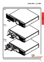
Page 8: ...Daker DK 1 2 3 kVA 29 EN Tower configuration setup A1 A1 A1 A1 A3 A2 Step 1 Step 2 ...
Page 9: ...30 4 Installation UPS battery cabinet optional A4 Step 1 Step 2 ...
Page 10: ...Daker DK 1 2 3 kVA 31 EN B2 B1 S3 90 Step 1 Step 2 Step 3 Step 4 ...
Page 11: ...32 4 Installation Step 5 Step 6 ...
Page 14: ...Daker DK 1 2 3 kVA 35 EN R1 R2 S T U1 U2 U3 V ...
Page 17: ...38 6 Battery replacement Step 1 Step 2 ...
Page 18: ...Daker DK 1 2 3 kVA 39 EN Step 3 Step 4 3 100 50 Step 4 3 100 51 3 100 52 ...


