


25
EN
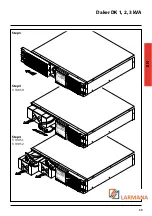
Daker DK 1, 2, 3 kVA
3 LCD Panel
1. LCD Panel
2. The green LED on steady indicates that the power supply network is within the 160-288 Vac
range.
3-4. The green LEDs indicate that the programmable Outlets 1 and 2 are present.
5. The orange LED indicates that the Bypass is active.
6. UPS alarm LED
7. UPS power on/buzzer silencing pushbutton
8. UPS power o
ff
pushbutton
9. Special functions access menu pushbutton, log in/out
10. Following screen selection pushbutton
11. Previous screen selection, or settings change pushbutton
12. Selection con
fi
rmation pushbutton
2
3
4
5
6
7
8
9
10
11
12
1
Summary of Contents for 0 3 100 51
Page 1: ... Part LE05334AC 07 13 01 GF Daker DK 1 2 3 kVA Manuel d installation Installation manual ...
Page 8: ...Daker DK 1 2 3 kVA 29 EN Tower configuration setup A1 A1 A1 A1 A3 A2 Step 1 Step 2 ...
Page 9: ...30 4 Installation UPS battery cabinet optional A4 Step 1 Step 2 ...
Page 10: ...Daker DK 1 2 3 kVA 31 EN B2 B1 S3 90 Step 1 Step 2 Step 3 Step 4 ...
Page 11: ...32 4 Installation Step 5 Step 6 ...
Page 14: ...Daker DK 1 2 3 kVA 35 EN R1 R2 S T U1 U2 U3 V ...
Page 17: ...38 6 Battery replacement Step 1 Step 2 ...
Page 18: ...Daker DK 1 2 3 kVA 39 EN Step 3 Step 4 3 100 50 Step 4 3 100 51 3 100 52 ...


