Encrypted Digital Wireless System
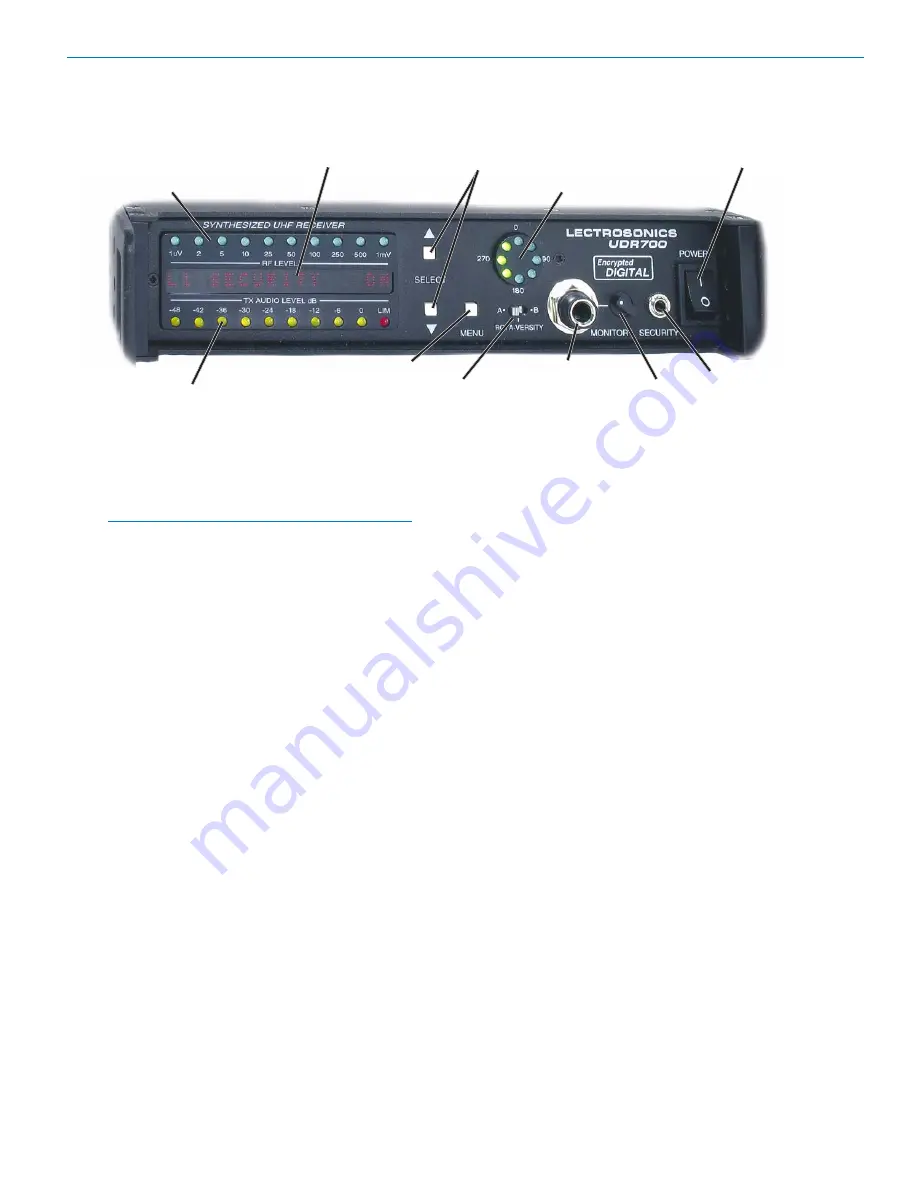
UDR700 Controls and Functions
UDR700 Front Panel
Information and Status Display
SELECT Up/Down Buttons
POWER On/Off Switch
RF Level Indicator
MENU Button
Antenna Phase Combining Indicator
Audio Monitor Jack
SECURITY Jack
Transmitter Audio Level
ROTA-VERSITY Switch
Audio Monitor Level Control
RF Level Indicator
A 10-segment LED strip indicates the level of the
incoming RF signal. The strip is calibrated to provide
accurate indications from 1 uV to 1 mV. The LEDs are
highly visible from a distance.
Note: A digital wireless receiver behaves differently
than an analog receiver during weak RF signal
conditions. The audio signal to noise ratio of an
analog receiver will gradually deteriorate as the RF
signal level drops, and the receiver will continue to
produce audio (accompanied by some noise) even
at very low RF levels. The signal to noise ratio of a
digital receiver remains largely unchanged as the
RF signal level drops, until suddenly, over a range
of just a few dB, the signal abruptly degrades and
then is muted altogether.
The RF Level Indicator can accurately display signals
as low as 1 uV to permit checking for interfering signals
just below the squelch threshold of the receiver. With
the transmitter turned off, the LEDs will indicate the
presence of interference.
Transmitter Audio Level
The 10-segment Transmitter Audio Level indicator strip
displays the modulation (audio level) of the incoming
signal. The strip is calibrated in 6 dB steps over an
expanded scale (54 dB) providing an extremely accu
rate visual “picture” of the signal dynamics.
Information and Status Display
A 16-segment Information and Status Display provides
information about the security level, selected frequency,
or tuning group, transmitter Frequency Select Switch
setting, TV channel, transmitter battery level and
system locked/unlocked status.
Menu Button
The MENU button steps the Information and Status
Display through six different displays used for setup and
operation. (See Information and Status Display Menus
and Functions and Installation and Operating Instructions.)
Select Up/Down Buttons
The SELECT Up/Down buttons are used to select
various options within each display selection and for
setting the operating frequency of the receiver.
Rota-Versity™ Switch
The Rota-Versity™ switch is a three-position switch
used to either enable diversity operation, or to tempo
rarily disable diversity operation (by selecting antenna A
or antenna B) for diagnostic purposes.
Antenna Phase Combining Indicator
Indicates the phase relationship between antenna A
and right for antenna B. Also provides a visual warning
if the Rota-Versity switch is not in the normal (centered)
position, or if one of the antennas is malfunctioning.
Power Switch
The Power switch applies AC or External DC power to
the unit. This switch, in conjunction with the MENU
button, can also be used to lock, or unlock the front
panel buttons (see Disabling Front Panel Buttons), and
in conjunction with the SELECT Down button, can used
to set the Security Level. (See Installation and Operat
ing Instructions, Setting the Security Level.)
Security Jack
The Security Jack is a 3.5 mm mono connector used to
set the security level of the associated transmitter(s).
(See Installation and Operation Instructions, Setting the
Security Level.)
Audio Monitor Level
The Audio Monitor Level controls the amplitude of the
audio output from the Audio Monitor Jack.
Audio Monitor Jack
The 1/4-inch, stereo, Audio Monitor Jack will drive a
wide variety of different types of headphones and can
also be used as a second high quality audio output to
drive recorders or other external audio devices.
Rio Rancho, NM
11
Summary of Contents for UDR700
Page 4: ...UDR700 UM700 UT700 LECTROSONICS INC 4 ...
Page 10: ...UDR700 UM700 UT700 LECTROSONICS INC 10 ...
Page 18: ...UDR700 UM700 UT700 LECTROSONICS INC 18 ...
Page 26: ...UDR700 UM700 UT700 LECTROSONICS INC 26 ...
Page 31: ...Encrypted Digital Wireless System Rio Rancho NM 31 ...
Page 35: ...Encrypted Digital Wireless System Rio Rancho NM 35 ...


