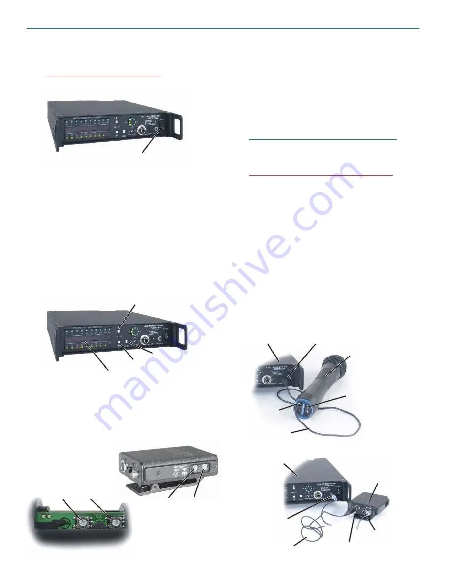
POWER Switch
UDR700 / UM700 / UT700
6)
Set the front panel POWER switch to On and
observe the POWER UP SEQUENCE. (See
Information and Status Display Menus and Func
tions.
Warning: Do not turn on the associated
transmitter(s)
.
7)
When the Main Tuning Menu appears observe the
RF Level Indicator LEDs. (If the Main Tuning Menu
is not displayed, press and release the MENU
button to step through the menu selections until it is
displayed.) If any of the RF Level Indicator LEDs
glow or blink, use the SELECT Up or Down button
to locate a clear channel (no RF activity) from one
of the current factory preset frequency group. If a
clear channel is not available using one of the
factory preset frequencies, press and hold the
MENU button, then press the SELECT Up or Down
button to tune across the entire 25.5 MHz fre
quency block (in 100 kHz steps) to locate one.
(See Information and Status Display Menus and
Functions, Main Tuning Menu and Group Tuning
Menu)
SELECT Down
MENU
SELECT Up
Information and Status Display
8)
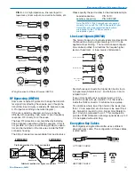
If necessary, install a fresh battery in the transmit
ter. (See UM700 Battery Installation and UT700
Battery Installation.) Set the Frequency Select
Switches on the associated transmitter to match
those identified in the receiver’s Main or Group
Tuning Menus (the two rightmost characters on the
Information and Status Display).
Coarse
Fine
UT700
Frequency Select Switches
(Inside Battery Compartment)
Coarse
Fine
Frequency Select Switches
UM700
9)
Determine the security level required. (See The
700 Series Encryption System.)
10)
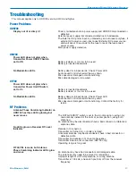
Turn the UDR700 Off, then press and hold the
SELECT Down button while turning the UDR700
back on. The display will show the current security
level. The default is Level 1.
11)
Use the SELECT Up or Down buttons to choose a
new security level, then press the MENU button to
finalize the security level selection process. The
Information and Status Display displays a message
indicating the level of security (Level 1, 2 or 3).
Note: Changing security levels requires that a new
key be sent to the transmitter before the system
will operate. (See Changing Security Level and
Setting or Resetting Encryption Key.)
Warning: In Security Level 3, both the transmitter
and receiver must be turned on and set to the
same operating frequency prior to setting the
Encryption Key.
12)
Press the MENU button to enter the Key Genera
tion Menu. “MAKE NEW KEY?” will be displayed in
the Information and Status Display with an “Up”
arrow to the message’s right. (See Information and
Status Display, Menus and Functions, Key Genera
tion Menu.)
13)
Press the SELECT Up button and follow the
directions on the Information and Status Display.
Eventually the prompt “NEW KEY TO TX ^” is
displayed.
15)
Connect the appropriate KEY CABLE Encryption
Cable between the transmitter and the UDR700
and turn on the transmitter.
UDR700
Security Jack
UT700 Key Cable
UT700
Power LED
Encryption
Key Link
UM700 Input Jack
Security Jack
UM700
UDR700
Modulation LEDs
UM700 Key Cable
LECTROSONICS, INC.
20
Summary of Contents for UDR700
Page 4: ...UDR700 UM700 UT700 LECTROSONICS INC 4 ...
Page 10: ...UDR700 UM700 UT700 LECTROSONICS INC 10 ...
Page 18: ...UDR700 UM700 UT700 LECTROSONICS INC 18 ...
Page 26: ...UDR700 UM700 UT700 LECTROSONICS INC 26 ...
Page 31: ...Encrypted Digital Wireless System Rio Rancho NM 31 ...
Page 35: ...Encrypted Digital Wireless System Rio Rancho NM 35 ...


