UDR700 / UM700 / UT700
UDR700 Rear Panel
AC Power
EXT Power
Input Connector
Connector
GND LIFT
Digital Audio AES-3id
AUDIO OUTPUT Jack
Analog Audio
ANT B
ANT A
PHASE Switch
Output Control
AC Power Supply
The UDR700 has a universal switching power supply
which operates on AC voltages ranging from 95 to 240
Volts, 50 or 60 Hz. Since the power supply is self
protected against line transients, short circuits, and over
current conditions, there is no external fuse.
EXT Power Connector
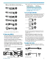
This 4-pin XLR jack is also provided for connecting to
an external power source (+11 to +17 VDC) if desired.
The EXT POWER Connector accepts a standard 4-pin
female XLR connector wire so that Pin 4 is positive and
Pin 1 is ground.
Analog Audio Output Control
A calibrated control on the rear panel adjusts the output
level in 5 dB increments, calibrated in dBu. This control
adjusts the absolute output level at the rear panel XLR
connector when the transmitter is fully modulated
(maximum audio level). The Analog Audio Output
Control is located after the output transformer allowing
the signal to noise ratio to remain constant regardless
of the control’s setting.
GND/LIFT Switch
The GND/LIFT switch either applies or removes chassis
ground from Pin 1 of the AUDIO OUTPUT jack. Lifting
the chassis ground is useful when AC hum is generated
by a ground loop.
Note: Ground loops can occur when the analog
audio output is connected to remote equipment
powered from a different AC main supply.
Phase 0/180
The PHASE 0/180 switch reverses the polarity of the
analog audio output signal.
Digital Audio Output - AES-3id
A BNC connector providing a digital audio output signal
conforming to the AES-3id standard.
Antenna Jacks
These are standard 50 Ohm BNC terminals for the RF
input to the receiver. Both antennas are required for
diversity mode (normal) operation.
UDR700 Iinformation and Status Display
Menus and Functions
Power Up Sequence
When the UDR700 is powered up, the Information and
Status Display will display three messages in sequence
followed by one of the three tuning menus (Main Tuning
Menu, TV Tuning Menu or Group Tuning Menu).
Buttons Enabled/Disabled
Security Level
Firmware Version/Decoder Firmware Version
S E C U R I T Y
L E V E L
1
B U T T O N S
E N A B L E D
U D R 7 0 0
V 3 . 0 / 3 . 0
The tuning menu displayed is the last tuning menu
displayed prior to the last time the UDR700 was turned off.
Enabling and Disabling the Buttons
The front panel control buttons (MENU, SELECT Up/
Down) can be disabled (locked) to prevent accidental
operational changes during use.
When the UDR700 is turned on, the first message
displayed on the Information and Status Display will be
either BUTTONS ENABLED or BUTTONS DISABLED.
If buttons are disabled, pressing any button causes the
message BUTTONS DISABLED to be displayed briefly
and no action will be taken.
LECTROSONICS, INC.
12
Summary of Contents for UDR700
Page 4: ...UDR700 UM700 UT700 LECTROSONICS INC 4 ...
Page 10: ...UDR700 UM700 UT700 LECTROSONICS INC 10 ...
Page 18: ...UDR700 UM700 UT700 LECTROSONICS INC 18 ...
Page 26: ...UDR700 UM700 UT700 LECTROSONICS INC 26 ...
Page 31: ...Encrypted Digital Wireless System Rio Rancho NM 31 ...
Page 35: ...Encrypted Digital Wireless System Rio Rancho NM 35 ...


