Hardware Manual for the DMC5400 Motion Controller
Tel: +086 0755-26434369 Email: [email protected] Web Site: www.leadshine.com
Page: 6/36
2. Remove the cover from your computer.
3. Before handling the PCI card, discharge any static buildup on your body by touching the metal case of the
computer. Hold the edge of the card and do not touch the components.
4. Set the jumpers on the DMC5400 card. See
“
Jumper & Switch Settings
”
section for more information. Connect
X2, X3 or X4 before installing the DMC5400 if it
’
s necessary. See
“
DMC5400 Connectors
”
section for more
information.
5. Select a 32-bit PCI slot.
6. Position the board into the PCI slot you have selected.
7. Secure the card in place at the rear panel of the system.
2.4 Jumper & Switch Settings
There are 11 jumpers (J1~J11) and one 4-bit DIP switch on the board for setting command signal types, EMG
signal, EL signals, and selecting external power supply or internal power supply. See figure 2.1 for distributions of
these Jumpers and Switch.
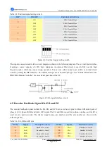
Figure 2.1: Sketch drawing of the DMC5400
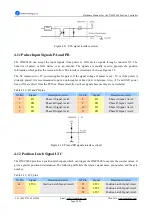
2.4.1 Command Signal Type Settings (J1~J8)
There are 8 jumpers (J1~J8) on the DMC5400 specifically for command signal type settings. The user can use
these jumpers to set PUL/DIR command signals of 1~4 axis to either single-ended (open collector) or differential.
The default setting is the single-ended mode. (J1~J8 are short circuit between pin2 and pin3.)
Figure 2.2: J1~J8 jumpers
Table 2-1: Command signal type settings
Pin Number of X1
Signal
Differential Output
Single-ended (Open collector) output
1
PUL0+ J1: short circuit between pin1 and pin2 J1: short circuit between pin2 and pin3
3
DIR0+ J2: short circuit between pin1 and pin2 J2: short circuit between pin2 and pin3
21
PUL1+ J3: short circuit between pin1 and pin2 J3: short circuit between pin2 and pin3
23
DIR1+ J4: short circuit between pin1 and pin2 J4: short circuit between pin2 and pin3


