Hardware Manual for the DMC5400 Motion Controller
Tel: +086 0755-26434369 Email: [email protected] Web Site: www.leadshine.com
Page: 27/36
“
Software Manual for the DMC5400 Motion Controller Motion Controller
”
.
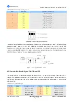
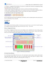
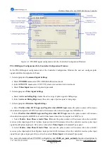
Figure 6.4: Servo control signal configuration tab (the Controller Configuration Window)
Servo Control Signal Configuration Tab (Controller Configuration Window)
In the Servo Control signal configuration tab of the Controller Configuration Window, the user can configure
in-position signals, alarm signals and encoder signals of all axes.
1. Select appropriate
INP Signal Settings
a. Select
Disable
in INP signal panel means disable In-Position feedback function, and the INP input port can
be used as a general purpose input when disable In-Position feedback function.
b. Select
Enable
in INP signal panel means enable In-Position feedback function. In this situation, the motion
status flag, namely the result from the
d5400_check_done
function has to wait for INP to be active before turning
into 1(motion stop status flag), even the controller has stopped output pulses actually.
c. Select
Active LOW
in INP signal panel means the active logic level of the In-Position signal is LOW level.
d. Select
Active HIGH
in INP signal panel means the active logic level of the In-Position signal is High level.
2. Select appropriate
Alarm Signal Settings
a. Select
Immediately Stop
in ALM signal panel means the controller stops output pulse command signals
immediately when the ALM signals are active.
b. Select
Stop with Deceleration
in ALM signal panel means the output PUL signals will decelerate at the
deceleration values specified by velocity profile setting functions when the ALM signals are active.
c. Select
Active LOW
in ALM signal panel means the active logic level of the Alarm signal is LOW level.
d. Select
Active HIGH
in ALM signal panel means the active logic level of the Alarm signal is High level.
3. Select appropriate
Encoder Counter Settings
a. Select 1
×
A/B
means count increments once every four quad states,
×
1 A/B
b. Select 2
×
A/B
means count increments once every two quad states,
×
2 A/B
c. Select 4
×
A/B
means count increments once every quad state,
×
4 A/B
d. Select
CW/CCW
means pulse from EA causes the counter to count up, whereas pulse from EB causes the


