Hardware Manual for the DMC5400 Motion Controller
Tel: +086 0755-26434369 Email: [email protected] Web Site: www.leadshine.com
Page: 21/36
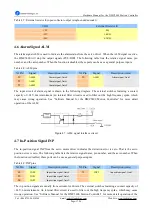
The input circuit of position latch signal is shown as Figure 4.13. The external switches featuring a contact
capacity of +24V, 6mA minimum. An internal filter circuit is used to filter out the high frequency spike, which
may cause wrong operation. See
“
Software Manual for the DMC5400 Motion Controller
”
for more detail
operation of the LTC.
Figure 4.13: LTC signal interface circuit
4.13 Emergency Stop Signal EMG
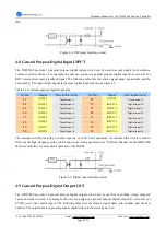
The emergency stop signal EMG is used to stop motion of all axes. Please check the EMG signal logic setting
(J11 jumper) and the EMG signal when the card can not work properly. The interface circuits are shown as Figure
4.14. The external switches featuring a contact capacity of +24V, 6mA minimum. An internal filter circuit is used
to filter out the high frequency spike, which may cause wrong operation.
Figure 4.14: EMG signal interface circuit
4.14 Typical Connection for One Axis
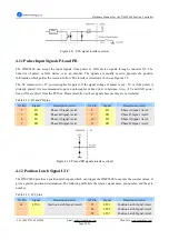
The DMC5400 has 2 end limit signal, 1 slow down signal, and 1 Origin position signal for each axis. For reliable
response and better anti-interference performances, all of these signals have filter circuits in their input circuits. A
typical connection for one axis is shown as Figure 4.15.
Figure 4.15: Typical connection for one axis


