background image

Sentinel Plus Press Brake Guarding System Operation Manual 

LS-CS-M-073 

Page 51 

Original Language Version: 1.04 

Released: 19/07/2017 

Once  a  menu  has  been  selected  the  parameters  can  be  navigated,  selected  and  edited. 
The  parameters  are  stored  in  non-volatile  memory  that  is  maintained  even  when  the 
Sentinel Plus system is powered down. 


Warning: 
The System menu does not contain any user configurable parameters . 
System  menu  parameters  must  only  be  configured  by  trained  and 
qualified Sentinel Plus installers. Setting incorrect parameter values in 
the System menu may render your machine inoperable.


8.1.1


Selecting Menu Parameters 

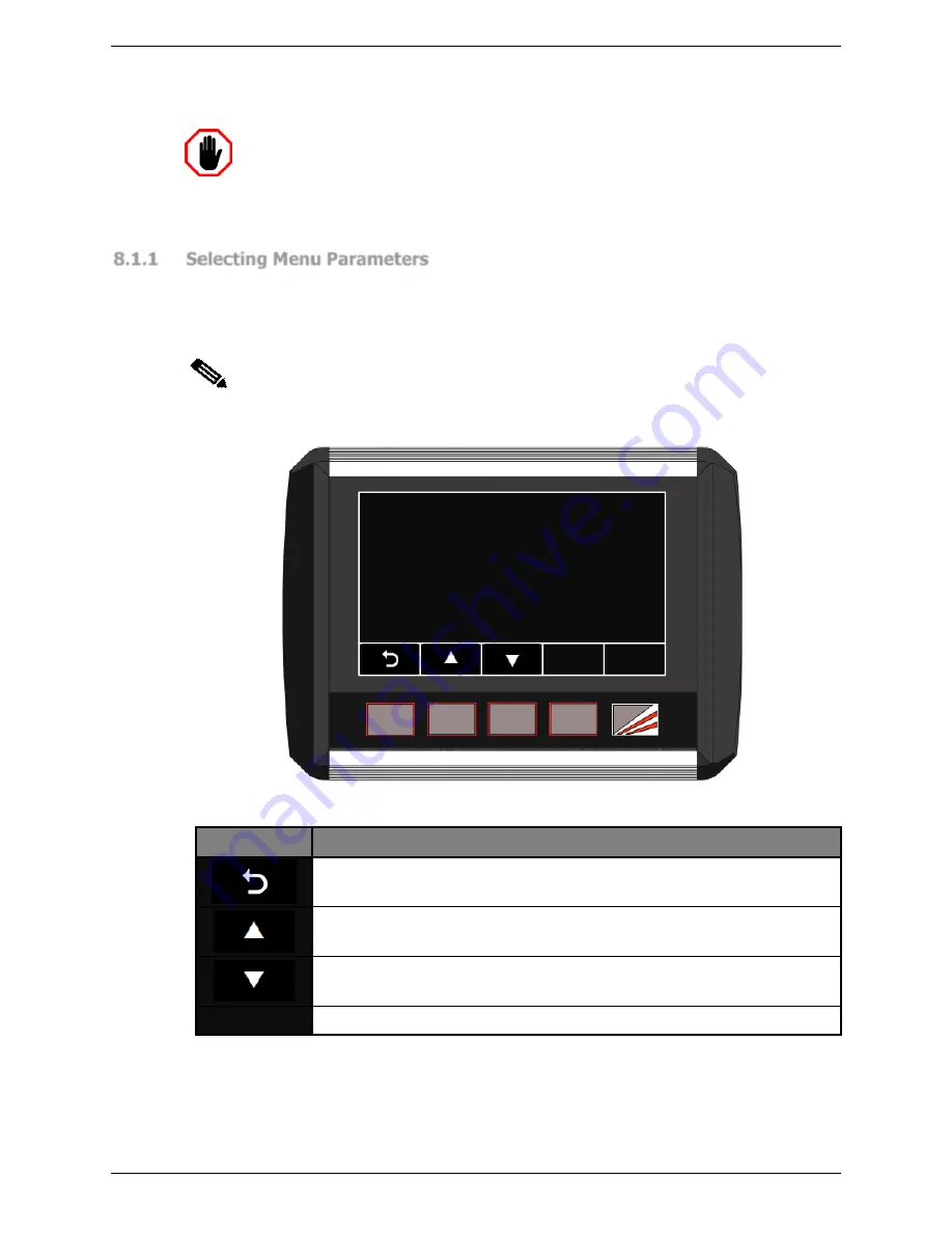
This section explains how to select and change the parameters in the Parameter List. For 
all  of  the  menus  (User,  Supervisor  and  System)  the  parameters  are  navigated  using  the 
Sentinel  Plus  buttons,  as  shown  in 

Figure  8-2

  and 

Table  8-2

.  The  arrow  buttons  step 

through the parameter list; the parameter is selected by pressing the 

ENTER

 button. 


Note: 

Lists  and  values  that  are  navigated  using  arrow  keys  always  appear  as  loops. 
When the end of the list is reached, the next button press will return the screen to 
the start of the list.


a

ENTER

Press UP and DOWN to browse menu then press ENTER  to select

USER PARAMETER 0

Buzzer on/off


Figure 8-2: Menu Parameter Screen 

Label 

Button Function 


This leaves the Parameter List and returns to the Menu screen. See 

Figure 5-2

 for an overview of the menu system. 


This changes the displayed parameter to the 

next

 parameter in the list 

(Parameter 0 

 Parameter 1 

 Parameter 2 etc.)


This changes the displayed parameter to the 

previous

 parameter in the 

list. (Parameter 2 

 Parameter 1 

 Parameter 0 etc.)


ENTER 

This selects the displayed item. 

Table 8-2: User/Supervisor/System Menu Buttons 

There are two types of parameters: 


Options

. The value for the parameter can be selected from a list of options.


Numbers

. The parameter takes a numerical value between 0 and 9999.


Summary of Contents for SENTINEL PLUS

Page 1: ...SENTINEL PLUS PRESS BRAKE GUARDING SYSTEM Operation Manual LS CS M 073 27 Action Road Malaga WA 6090 Australia PO Box 2368 Malaga WA 6944 Australia 61 8 9249 4388 61 8 9249 6011 info lazersafe com...

Page 2: ...l Plus Press Brake Guarding System Operation Manual LS CS M 073 Page 1 Original Language Version 1 04 Released 19 07 2017 Document Status Document Reference Code LS CS M 073 Version 1 04 Released 19 0...

Page 3: ...nual 14 03 2016 1 01 Added External Stop at Mute Added mute reset message Added E Stop menu Added Restricted mode crawl description 14 02 2017 1 02 Clarified the note in Special Tools Updated Setup mo...

Page 4: ...oft Corporation in the U S A and or other countries The content of this manual is supplied for informational use only is subject to change without notice and should not be construed as a commitment by...

Page 5: ...uropean Union 11 2 3 3 Requirements for Retrofitted Systems All Locations 11 2 3 4 Equipment Alterations 11 3 System Overview 12 3 1 Key Benefits 12 3 2 System Components 13 3 3 Optical Protection Ove...

Page 6: ...Select Screen 31 5 6 Menu Screen 32 5 6 1 User Guides 33 5 7 Info Screen 34 5 7 1 System Information 34 5 7 2 Machine Information 35 6 System Operation 36 6 1 Power up 36 6 2 Start up Test 36 6 3 Sett...

Page 7: ...3 Parameter 2 Mute Stop Button Functionality 55 8 3 4 Parameter 3 Mute Off Set Distance 55 8 3 5 Parameter 4 Language 56 8 3 6 Parameter 5 Guard Type Selection 56 9 Operator Instruction and Demonstrat...

Page 8: ...Sentinel Plus Press Brake Guarding System Operation Manual LS CS M 073 Page 7 Original Language Version 1 04 Released 19 07 2017 This page has been left intentionally blank...

Page 9: ...ed safety practices 1 3 Document Organisation This manual is organised into the following chapters 1 About This Manual 2 Critical Safety Information 3 System Overview 4 LZS 005 R Operation 5 The Senti...

Page 10: ...ould result in equipment damage Warning This symbol indicates danger You are in a situation that could cause bodily injury Before you work on any equipment be aware of the hazards involved with electr...

Page 11: ...le protective equipment must be worn by the operator at all times 2 2 Special Warnings To ensure the highest possible degree of safety in operating a press brake fitted with the Sentinel Plus Press Br...

Page 12: ...the Sentinel Plus system must comply with the relevant local regulations that apply to machine safety and accident prevention 2 3 3 Requirements for Retrofitted Systems All Locations The combination...

Page 13: ...system can be installed either at the time of manufacture or as a retrofit to a press brake already in service Figure 3 1 Sentinel Plus Press Brake Guarding System Key Features Automatic Mute Point S...

Page 14: ...tem comes as standard with the LZS 005 R Block Laser transmitter and receiver pair The transmitter and receiver are mounted on the upper beam of the press brake allowing the operator to remain close t...

Page 15: ...LZS 005 R Block Laser The Sentinel Plus system employs a LZS 005 R Block Laser transmitter and receiver The transmitter projects a square beam of laser light approximately 80mm wide by 50mm high that...

Page 16: ...the tool tip is outside of the target area the operator will be directed to physically move the LZS 005 R receiver so that the tool tip lies within the target area Section 4 1 explains how the operat...

Page 17: ...high speed If any sensor remains obstructed the system will force the tools to close in safe speed only with the optical protection muted and display the message LASERS INACTIVE until the bend is com...

Page 18: ...gions become active again once the tools are opened 3 5 2 Tray Mode When the Tools are Closing If there is no obstruction to any of the guarded regions then the system operates as it does in Normal Mo...

Page 19: ...ode 3 7 Field Muted Mode Warning NO OPTICAL PROTECTION IN FIELD MUTED MODE In Field Muted mode all optical guarding is deactivated Although the Sentinel Plus Press Brake Guarding System ensures that t...

Page 20: ...n for the operator Figure 3 7 Special Tool Types left to right Large V Large Radius Flattening Depending upon the size and shape of the tool the Sentinel Plus may have to increase the mute point If th...

Page 21: ...PROTECTION AREA If the tool is large enough to present a crushing hazard outside of the protection area provided by the laser guards it is necessary to provide additional safety measures such as incre...

Page 22: ...lso be exercised in Tool Set up mode Tool Set up Mode is only required for some models of press brakes In Tool Set up mode the Sentinel Plus will attempt to restrict the tool closing speed to crawl sp...

Page 23: ...rtain Mode 3 12 Mute Mode Restricted optional The Sentinel Plus System may be installed on machines that do not support dual speed operation However if these machines cannot close tools at safe speed...

Page 24: ...onitored during normal operation If safe speed is required for example if the sensors are muted but the pressing beam is moving down beyond safe speed an emergency stop condition is triggered The oper...

Page 25: ...he tool silhouette on the receiver window Figure 4 1 Block Laser Receiver Alignment When the transmitter and receiver have been positioned correctly the automatic tool alignment can be performed Figur...

Page 26: ...d by an obstruction or by a poor alignment The image captured by the receiver is too light to locate any tool silhouette This may be caused by a poor alignment or very high levels of ambient light shi...

Page 27: ...the original position is maintained by the clamp handle assembly then release the locking pin Figure 4 6 Mounting Brackets Warning When adjusting the bracket handle ensure that the bottom of the brack...

Page 28: ...19 07 2017 4 4 Periodic Alignment Check The alignment of the transmitter as described in Section 4 1 above should be checked at the following times After system start up After each tool change After e...

Page 29: ...Info User User Guides System Machine System Supervisor Tool Setup Requires Supervisor access code Parameter 0 Parameter 1 Parameter N Parameter 0 Parameter 1 Parameter N Parameter 0 Parameter 1 Param...

Page 30: ...iple errors have occurred press the reset button twice If the error cannot be cleared by pressing the reset button multiple times then a fault or emergency stop condition has occurred that must be cor...

Page 31: ...This Condition Code is also displayed in the lower right hand corner of the Status window Operation Pending If the PGS 3 Safety Controller requires that an operation is to be performed to verify the s...

Page 32: ...The F M or R LED is ON when the region is obstructed F M R Figure 5 5 Front Middle and Rear Obstruction Indicators 5 5 Mode Select Screen The other screen used in most typical machine operations is t...

Page 33: ...red in the Supervisor menu BACK GAUGE This button toggles the Back Gauge mode Table 5 2 Mode Select Screen Buttons 5 6 Menu Screen The Menu screen gives access to the menus that are used to configure...

Page 34: ...ed selected and edited The parameters are stored in non volatile memory that is maintained even when the Sentinel Plus system is powered down Refer to Section 8 for detailed instructions on how to nav...

Page 35: ...3 and the panel to verify the integrity of the communications link The Comm status field shows the state of the communications link Connected or Not connected HMI type The User Interface Panel or HMI...

Page 36: ...i__104 FPGA version Approx slow point 2mm MSD 13mm BLR version BL Table 5 5 Info Screen System Information 5 7 2 Machine Information Machine Information is displayed by pressing the MACHINE INFO menu...

Page 37: ...screen Press foot pedal or any button to continue Figure 6 1 Sentinel Plus Idle Screen The LZS 005 R optical guarding system performs a self test and initialises its optical system When the optical p...

Page 38: ...00 STATUS BL Figure 6 3 Start up Test Screen Before performing the overrun test check the following Open the tools to a minimum opening of 100mm Check that the transmitter and receiver are correctly a...

Page 39: ...t the machine emergency stop circuit and or restart the hydraulic pump 6 3 Setting the Mute Point After the start up test is complete the operator will be prompted to set the mute point by the message...

Page 40: ...oot pedal The Status screen changes to a red background and prompts the operator to CONFIRM MUTE POINT PRESS SET BUTTON as shown in Figure 6 7 If an external mute lamp has been installed the lamp will...

Page 41: ...ged the mute point must be reset When the machine is at TDC press the MUTE RESET button If the machine is not at TDC the message Open tools to enable button function will be displayed in the Status wi...

Page 42: ...m memory and does not need to be set again when changing to Tray Box mode If the operator needs to reset the mute point while in Tray Box mode the procedure is the same as described in Section 6 4 exc...

Page 43: ...bled Disabled ON Disabled When the system enters Field Muted Mode the screen will appear as shown in Figure 6 13 The FIELD MUTED button turns green the Status screen turns red to indicate that the opt...

Page 44: ...with the lasers above the mute point and clear of any obstructions If these conditions are not met the Status window will display the message Open tools to enable button function Note The MUTE STOP bu...

Page 45: ...ndependent of the User Interface Panel and cannot be blocked in the Supervisor menu 6 9 Selecting Back Gauge Mode Back Gauge mode is selected from the Mode Select screen From the Main screen press the...

Page 46: ...TOOL SETUP button is pressed the screen prompts the operator to enter the Supervisor access code as shown in Figure 6 17 If the code is correct the panel proceeds to the Tool Setup mode screen and the...

Page 47: ...selected during installation E Stop Option 1 If any side gate is open no down movement is allowed The E Stop cannot be cleared until the door is closed E Stop Option 2 If one side gate is open and all...

Page 48: ...this is the pinch or zero opening point The operator then confirms this position by pressing the SET button and the system automatically sets the mute point at 6mm 1 4 above the zero opening position...

Page 49: ...itten into the panel s non volatile memory and the system will return to the parameter list Press the button to return to the Main screen LC Figure 7 2 Sensor Window Light Curtain Mode The Sensor wind...

Page 50: ...ntical to operation with laser guards with the exceptions that the guard modes Tray mode Tray 2 mode and Back Gauge mode are not required and cannot be selected Field Muted mode and Stop at Mute mode...

Page 51: ...ccess the Supervisor level menu This menu contains machine site specific parameters that are set during the installation of the Sentinel Plus Press Brake Guarding System The System menu is not describ...

Page 52: ...e 8 2 The arrow buttons step through the parameter list the parameter is selected by pressing the ENTER button Note Lists and values that are navigated using arrow keys always appear as loops When the...

Page 53: ...anged is underlined by a cursor starting with the left most digit i e the digit 1 in Figure 8 3 below The buttons are pressed to increment or decrement the value of the underlined digit Once the digit...

Page 54: ...the system will return to the parameter list 8 2 2 Parameter 1 Special Tools Mode Special Tools mode can be enabled disabled by this user selectable parameter This parameter has two options DISABLED...

Page 55: ...erator is prompted to enter the Supervisor level access code as shown in Figure 8 6 This is a numeric parameter as described in Section 8 1 3 and shown in Figure 8 3 Note The factory default superviso...

Page 56: ...uted Mode DISABLED OFF The button is disabled and Field Muted mode cannot be selected Use the buttons to navigate the options Changes can be abandoned at any time by pressing the button When the desir...

Page 57: ...e written into the panel s non volatile memory and the system will return to the parameter list 8 3 6 Parameter 5 Guard Type Selection The Sentinel Plus system has the option of supporting light curta...

Page 58: ...strate the automatic tool alignment and explain the diagnostics signals given by the receiver LEDs Demonstrate how the receiver detects the laser in segments using a 4 mm Allen key is usually convenie...

Page 59: ...mode including the need for a confirmation pedal press at the beginning of each stroke Explain the reason for Back Gauge mode and the elevated rear sensor mute height 16mm 9 6 Field Muted Mode Refer...

Page 60: ...ons Using each mode of the system have the operator bend some test pieces of material and also making sure to utilise the Tray Box mode for a demonstration of the operation during box bending Ensure t...

Page 61: ...e how to select Tool Set up mode via the Sentinel Plus User Interface Panel Explain that a tool alignment must be performed before entering Tool Set up mode Explain that in Tool Set up mode although t...

Page 62: ...ompany Representatives ________________________________ ________________________________ ________________________________ ________________________________ ________________________________ ____________...

Page 63: ...de or lacquer thinner to clean the window 1 Dampen a soft non abrasive cloth or chamois with the cleaning solution wring out any excess liquid 2 Wipe the windows of the transmitter and receiver clean...

Page 64: ...y HMI Human Machine Interface i e the User Interface Panel MSD Manufacturer s Stopping Distance The distance that the beam typically travels after a beam stop has been initiated as stated by the Press...

Reviews: