


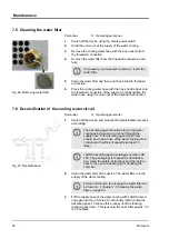


6.3
Screen displays
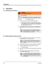
The default display is the indication shown in the screen if no other
operations such as configuring settings are being performed. The
actual temperature of the machine is shown in the default display.
The machine menu with possible settings can be invoked using the
ENTER button.
Further information about the menu structure and the
menu navigation can be found in
display and menu items’ on page 38
.
The display flashes when a menu item in the screen has been
selected. The setting can now be made. The value entered is
applied when the setting is confirmed.
6.4
Specifying the setpoint temperature
You specify a setpoint for the temperature control. This value
specifies to which temperature the heat transfer liquid will be
cooled. The upper and lower temperature limit values of the device
have been set to the default values 45.0 °C and 5.0 °C. The tem-
perature limits define the temperature range of your application, i.e.
in which range any temperature control can take place. A warning
is output by the device if the temperature is outside the limits. This
range is necessary so that no unnecessary warnings are output
during transient conditions of the temperature regulation. The
default values can be limited subsequently depending on the heat
transfer liquid.
For operation of the device with Aqua 90, the temperature setpoint
must not be set smaller than 5 °C. Also use the lower temperature
limit value
Lo
‘Lower temperature limit value’ on page 42
and
set this to 3 °C so that a warning is output for lower temperatures.
The yellow LED on the device lights if any temperature setpoint or
actual temperature is less than 5 °C. It warns about incorrect use
of the heat transfer liquid and consequential damage to the device.
If the device is operated with liquid temperatures below
5 °C, Kryo 30 (glycol / water) must be used in the device
as heat transfer liquid.
Default display
Fig. 13: Default display
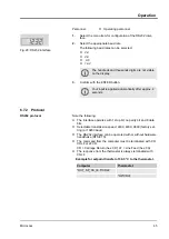
Menu
Editing display
Relationship between temperature
setpoint and temperature limit
values
Operation
Microcool
40
Summary of Contents for MC 250
Page 39: ...Fig 12 Menu Operation Microcool 39...
Page 56: ...Indication on the display Description NTC sensor break NTC short circuit Faults Microcool 56...
Page 67: ......
Page 68: ......
Page 70: ......
Page 71: ......