


View of flange connector (front) or solder side coupling socket
Max. 30 V DC; 1 A
Fig. 11: Flange connector (front) in idle state
1
Normally open contact
2
Centre
3
Normally closed contact
Idle state
The device is in idle state when it is switched off and in the
case of failure.
Pins 1 and 2 are open.
Pins 3 and 2 are closed.
GO state
The device is in GO state immediately after switching on and
during normal operation without faults.
Pins 1 and 2 are closed.
Pins 3 and 2 are open.
Note the following:
The equipment connected to the low voltage inputs and out-
puts must have safe separation from dangerous voltages
according to DIN EN 61140 such as by double or reinforced
insulation according to DIN EN 60730-1 or DIN 60950-1.
Only use shielded connection cables; connect the shield to the
connector case. Cover unused plug connections with protective
caps.
Before commissioning
Microcool
31
Summary of Contents for MC 250
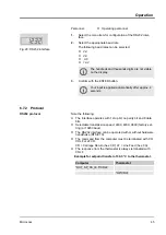
Page 39: ...Fig 12 Menu Operation Microcool 39...
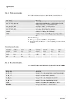
Page 56: ...Indication on the display Description NTC sensor break NTC short circuit Faults Microcool 56...
Page 67: ......
Page 68: ......
Page 70: ......
Page 71: ......