
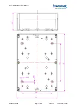


ICS-6-DLSM Instruction Manual
01692-53-000
Page 9 of 20
Issue 3 30 January 2020
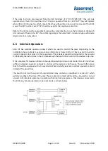
4.2 Control
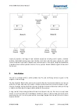
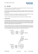
The switching unit is controlled by four contacts, two of which must only be closed in one-room
mode (divider or interconnecting door open) and the other two must only close in two-room mode
(divider/interconnecting door closed).
The two contacts which close in one-room mode are wired to J31 pins 1 and 2, and J31 pins 3 and 4.
The two contacts which close in two-room mode are wired to J34 pins 1 and 2, and J34 pins 3 and 4.
Switches shown in two-room mode, i.e. when divider is closed
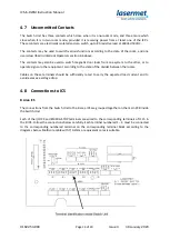
4.3 Safety Circuits
The A area door contacts and emergency stop buttons are wired as usual to the A ICS. Refer to the
ICS-6 manual.
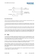
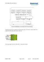
The B area door contacts and emergency stop buttons are not wired to the B ICS. Instead they are
connected to ‘B Area’ terminals in the Switch Unit, terminals J11, 12, 13, 15, 16, 28. They are
connected in exactly the same as they would be if they were inside the ICS. Each switch must have
two contacts which close when the door is closed, or the emergency stop button is not pressed. One
contact is wired across the outer two terminals, and the other contact across the middle two
terminals. Refer to the ICS-6 manual for more information and diagrams.
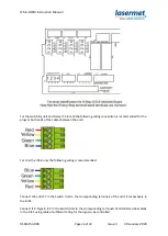
Any unused terminal blocks in J11, 12, 13, 15, 16 must have a jumper fitted between the outer two
terminals, and another jumper fitted between the middle two terminals in the same way as they
would in an ICS-6.


