


ICS-6-DLSM Instruction Manual
01692-53-000
Page 7 of 20
Issue 3 30 January 2020
4
Wiring
This section gives an overview of the general wiring principles as a guide to cable routing. More
detailed information for each function is given in succeeding sections.
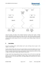
When wiring such a system the general principle is to wire all the B area input equipment (door
contacts, override switches, keypads etc.) to the switching unit instead of the B ICS.
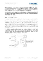
The B ICS interlock operators may be wired directly to their controlled devices (shutters, lasers,
maglocks) if they are only to work in two-room mode. Any outputs which have to work in both
modes must be cabled through the switching unit so that they can be controlled by the A ICS in one-
room mode. Note that the switching unit has three contacts which are closed in each mode and the
system should be designed with this limitation in mind. The A ICS must have sufficient spare
interlock operators to do this and a 9-way interlock board is a likely requirement for the A ICS in this
instance.
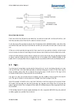
The signs in both areas are controlled by terminals inside the switching unit, not by the ICS’s. If the
signs are 24VDC powered, then they can be run off the switching unit 24V out terminals so that they
all work in both modes. If the loading is too great for the signs to be powered by one of the ICS PSU’s
then a separate power supply may be used. Mains powered signs may also be used, switched
through the terminals in the switching unit.
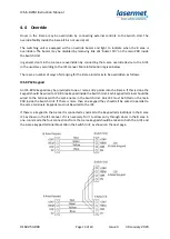
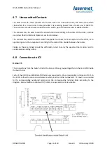
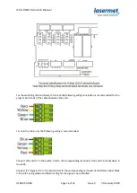
The switching unit will then have cabling to the A and B ICS’s as shown below. Note that there are 3
cables to the A ICS and 8 cables to the B ICS. An additional 2-core cable is required to run from the B
ICS to the switching unit for every B area interlock operator contact that has to pass through the
switching unit such that it will operate in one-room mode.
It may be more efficient to use two 16-core cables or one 24-core cable for the signal connections
between the B ICS and the switching unit as this will save four or five cables.
The following list suggests stranded cable with 0.2mm2 strands, the number of strands per core is
recommended.
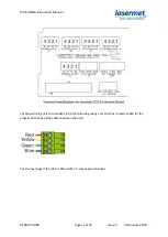
A ICS
24V and 12V Power
3-core 16 or 24 strand
Sign Control
3-core 16 or 24 strand
ICS/Output Monitor
4-core 7 strand
B ICS
Safety Circuits
4X 4-core 7 strand
Estop Circuit
4-core 7 strand
24V and 12V Power
3-core 16 or 24 strand
Sign Control
3-core 16 or 24 strand
ICS/Output Monitor
4-core 7 strand
Interlock Operators
If required to operate in one-room mode.


