LTI TruSense S300 Series Integration Manual 3nd Edition
Page 83
Copyright © [2016] Laser Technology, Inc. All Rights Reserved. Unauthorized duplication, in whole or in part, is strictly prohibited.
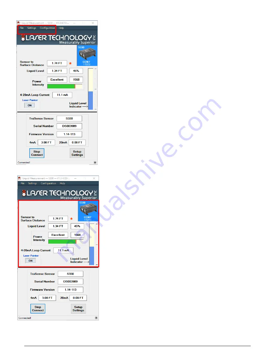
1. File: This will open three options. (See Figure 9)
1.1. Save Setting: Will allow the naming and saving current
configuration of the sensor to a file for back up.
1.2. Upload Setting: Will load and reconfigure sensor from saved
configuration file.
1.3. Exit: Will exit program.
2. Settings: This will allow the user to manually configure COM port and
Baud Rate. (See Figure 9)
3. Configuration: This will open three user change sensor functions. (See
Figure 9)
3.1. Reset Factory Defaults: This will reset all settings back to factory
defaults.
3.2. Change Offset: This will allow the user to set zero point of the
sensor to fine adjust to the installation site.
3.3 Change Instrument Baud Rate: The will allow the user to manually
change the RS-232 baud rate.
4.
Sensor to Surface Distance: Once the sensor is configured into the
installation site, this is the distance from sensor to liquid surface.
(See
Figure 10)
5.
*
:
Flashes on when measurement level and current loop are being updated.
(See Figure 10)
6.
Liquid Level: Once the sensor is configured into the installation site, there are
three indicators.
(See Figure 10)
6.1.
This is the distance from the bottom of the vessel to the surface of the liquid.
6.2.
Once the sensor is configured into the installation site, liquid level
percentage is the calculated percent of full.
6.3.
Liquid Level Indicator: Once the sensor is configured into the
installation site, is a graphical bar gage representation of liquid level of
vessel.
7.
Power Intensity: Once the sensor is configured into the installation site, there
are three indicators for laser return power intensity.
(See Figure 10)
7.1.
Intensity: Excellent, Good, Fair, and Poor.
7.2.
Power Intensity Return Value (Scale 0-2000)
7.3.
Bar graph with peak power indicator(Red Line)
8.
4-20mA Loop current: This is a calculated current displayed based on the
actual level being measured.
(See Figure 10)
9.
Laser Pointer: This will allow the user to turn on or off the visible laser
pointer.
(See Figure 10)
1
2
3
4
5
6.2
6.3
7.1
7.2
7.3
8
9
6.1
Figure 10: Main Window
Figure 9: Main Window


