background image

LT-1000 User & Installation Manual 


Installation 

Lars Thrane A/S 

www.thrane.eu 

16 of 42 

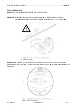
Step 3: Unpack the LT-1000 NRU and make a record of the unit serial number for support or warranty issues 
that could occur in the future. 


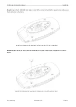
Step 4: Remove cap for DIP-switch setting. Remember to re-insert the cap after configuration of the DIP-
switch. 


F

IGURE 

20:


R

OOF 

M

OUNT INSTALLATION 

S

TEP 

3


(

BOTTOM SIDE OF THE 

LT-1000


NRU) 


F

IGURE 

21:


R

OOF 

M

OUNT INSTALLATION STEP 

4


(

REMOVE CAP FOR 

DIP-

SWITCH SETTING

Summary of Contents for LT-1000 NRU

Page 1: ...User Installation Manual LT 1000 NRU Document Number 95 100178 REV 1 00 Release date January 19 2016 Copyright Lars Thrane A S Denmark ALL RIGHTS RESERVED...

Page 2: ......

Page 3: ...Lars Thrane A S is not responsible for the content or accuracy of any translations or reproductions in whole or in part of this manual from any other source Copyright 2016 Lars Thrane A S All rights...

Page 4: ...ement WARNING Do not disassemble Do not disassemble or modify this equipment Fire electrical shock or serious injury can result WARNING Compass safe distance The minimum compass safe distance is 0 3 m...

Page 5: ...ARNING A Warning is an Operation or Service procedure that if not avoided may cause a hazard situation which could result in personnel death or serious injury NOTE A Note provides essential informatio...

Page 6: ...mounting and installation details with a step by step instruction for both pole and roof mount installations Connecting a description of the unit connector 8 pin multi cable connecting to NMEA 0183 co...

Page 7: ...LT 1000 User Installation Manual Lars Thrane A S www thrane eu v Record of Revisions Rev Description Release Date Initials 1 00 Original document January 19 2016 PT...

Page 8: ...INSTALLATION 5 CONNECTING 20 DEVIATION CALIBRATION 27 CONFIGURATION USING LT SERVICE TOOL 29 SERVICE AND REPAIR 32 TROUBLESHOOTING 33 APP A OUTLINE DRAWINGS 34 APP B PERFORMANCE 36 APP C SPECIFICATION...

Page 9: ...etic variation based on the World Magnetic Model WMM Compensation of soft and hard iron deviation Built in magnetometer calibration algorithm Receive and track multiple satellite systems GPS GPS GLONA...

Page 10: ...e Connecting on page 20 Step 3 Calibrating the Unit see Deviation calibration on page 27 Step 4 Configuring the Unit see Configuration using LT Service Tool on page 29 and Mounting offset adjustment o...

Page 11: ...native DIP switch settings are 38 400 baud NMEA 0183 and Terminated NMEA 2000 Mounting considerations Mount the unit on a rigid structure with a minimum of exposure to vibration and shock Mount the un...

Page 12: ...l on how to use the LT Service Tool to verify a subsequent calibration Configuration optional Use the LT Service Tool for optional configuration and offset adjustment of the LT 1000 NRU The LT Service...

Page 13: ...ns For optimum system performance some guidelines on where to install or mount the LT 1000 NRU must be followed It is recommended to mount the unit in a location with as much free line of sight as pos...

Page 14: ...ugh the pole mount It is recommended not to use pneumatic tools for cleaning the LT 1000 NRU especially at a short distance and directly at the split between the top and bottom part of the enclosure P...

Page 15: ...record of the unit serial number for support or warranty issues that could occur in the future Step 2 Remove cap for DIP switch settings Remember to re insert the cap after configuration of the DIP s...

Page 16: ...ct to pole mount installation IMPORTANT Make sure that there are no magnetic disturbances see Mounting and installation considerations on page 5 for for details or compass within 0 3 m 1 ft of the LT...

Page 17: ...LT 1000 User Installation Manual Installation Lars Thrane A S www thrane eu 9 of 42 FIGURE 11 POLE MOUNT INSTALLATION STEP 4 LOCATE AN APPROPRIATE LOCATION...

Page 18: ...nstallation Manual Installation Lars Thrane A S www thrane eu 10 of 42 FIGURE 12 POLE MOUNT INSTALLATION STEP 4 LOCATE AN APPROPRIATE LOCATION FIGURE 13 POLE MOUNT INSTALLATION STEP 4 LOCATE AN APPROP...

Page 19: ...hrane A S www thrane eu 11 of 42 Step 5 Complete the internal or external cable routing Feed the communication cable through the pole mount and install the cable plug FIGURE 14 POLE MOUNT INSTALLATION...

Page 20: ...LT 1000 User Installation Manual Installation Lars Thrane A S www thrane eu 12 of 42 FIGURE 15 POLE MOUNT INSTALLATION STEP 5 EXTERNAL ROUTING OF THE COMMUNICATION CABLE...

Page 21: ...ation Lars Thrane A S www thrane eu 13 of 42 Step 6 Fasten the pole mount by securing the two stainless A4 screws onto the LT 1000 NRU as illustrated in Figure 16 FIGURE 16 POLE MOUNT INSTALLATION STE...

Page 22: ...e pinol screw in the pole mount NOTE Final precision tuning of the Heading offset can be performed using the LT service tool see Configuration using LT Service Tool on page 29 IMPORTANT The pinol scre...

Page 23: ...ation considerations on page 5 for details or compass within 30 cm 1 ft of the LT 1000 NRU Step 2 Measure and mark the installation holes in accordance with the drawing Use the enclosed two stainless...

Page 24: ...e unit serial number for support or warranty issues that could occur in the future Step 4 Remove cap for DIP switch setting Remember to re insert the cap after configuration of the DIP switch FIGURE 2...

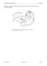
Page 25: ...refer to DIP switch and LEDs on page 21 for correct DIP switch settings Step 6 Mount and secure the two stainless A4 screws with securing disc from the pole mount FIGURE 22 ROOF MOUNT INSTALLATION STE...

Page 26: ...Adjust the heading before final clamping of the two self cutting stainless screws Step 8 Connect the communication cable FIGURE 24 ROOF MOUNT INSTALLATION STEP 7 FINAL CLAMPING OF THE TWO SELF CUTTIN...

Page 27: ...Thrane A S www thrane eu 19 of 42 Step 9 Install the simple cut end of the communication cable according to the details provided in Connecting on page 20 FIGURE 26 ROOF MOUNT INSTALLATION STEP 9 INST...

Page 28: ...ge 5 The communication cable is available in two lengths 10 or 30 meters The LT 1000 NRU is delivered including a 10 meter cable simple cut The communication cable color and connector pin assignment i...

Page 29: ...ctory However the installer should always check the settings of the DIP switch prior to an installation Make sure to hold the LT 1000 NRU as illustrated on Figure 30 when reading and configuring the D...

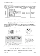
Page 30: ...00 baud see DIP switch and LEDs on page 21 Check that both the NMEA 0183 receive device and the LT 1000 NRU have the same GND reference as illustrated in Figure 32 and Figure 33 IMPORTANT It is recomm...

Page 31: ...two possibilities for the LT 1000 NRU to be connected to an NMEA 2000 network Open or Terminated A DIP switch in the LT 1000 NRU shall be configured depending on the installation The default setting f...

Page 32: ...ortened to a maximum length of 6 meters as defined in the NMEA 2000 standard for a drop cable NMEA 2000 Terminated If the LT 1000 NRU is installed as illustrated in Figure 38 then the DIP switch must...

Page 33: ...NOTE The LT Service Tool will automatically detect all LT Navigation devices which are connected to the PC s peripheral interfaces USB and serial Make sure that Tx and Rx wires are connected correctl...

Page 34: ...link than the RS 232 interface The LT 1000 NRU is supporting both RS 422 and RS 232 communicating link to the LT Service Tool Serial port RS 232 Illustration of a RS 232 interface in between a serial...

Page 35: ...g data if not corrected To compensate for deviation it is necessary to complete a deviation calibration of the magnetometers after installation of the LT 1000 NRU IMPORTANT The LT 1000 NRU will indica...

Page 36: ...econds SOG 2 12 knots Step 2 Make a full circle 360 450 clockwise or counterclockwise ROT 2 6 degrees second 1 3 minutes pr circle SOG 2 12 knots Step 3 Make a full circle 360 450 in opposite directio...

Page 37: ...ial interface in order to communicate with the LT Navigation devices The baud rate is either 4 800 or 38 400 baud configured on the LT 1000 NRU DIP switch see DIP switch and LEDs on page 21 NOTE It is...

Page 38: ...s Monitoring CM o General status Monitoring of NMEA 0183 data o Live NMEA 0183 sentences to inspect valid output from the LT 1000 NRU device Live navigations data o Navigation window to display live d...

Page 39: ...vice Tool command set heading offset offset or set heading heading to adjust the heading offset of the installation It is recommended to perform a bearing against a known object on the sea chart and t...

Page 40: ...the distributor dealer 1 Make sure to have the product name LT 1000 NRU Part Number P N 51 100142 and the unit serial number S N XXXXXXXX identified The unit serial number is listed on the outside of...

Page 41: ...g GPS Environmental Check that the LT 1000 NRU is supporting the expected NMEA 2000 PGNs see App E NMEA 2000 on 40 6 Using NMEA 0183 check your navigation equipment for correct baud rate Check that th...

Page 42: ...LT 1000 User Installation Manual App A Outline Drawings Lars Thrane A S www thrane eu 34 of 42 App A Outline Drawings LT 1000 with Pole Mount...

Page 43: ...LT 1000 User Installation Manual App A Outline Drawings Lars Thrane A S www thrane eu 35 of 42 LT 1000 Roof Mount...

Page 44: ...x cold acquisition 26 s Speed 0 1 knot 0 1 knot 0 to 970 knots Roll Pitch Static 0 5 rms 0 1 90 Rate of turn 1 s 0 1 s 0 to 45 s Air Pressure 1 hPa 0 1 hPa 800 to 1100 hPa Air Tempera ture4 1 C 1 8 F...

Page 45: ...in Temperature operational ambient 40 C to 55 C 40 F to 131 F Temperature storage ambient 40 C to 85 C 40 F to 185 F Vibration operational IEC 60945 sine Proprietary Maritime Random profile 240 h Vibr...

Page 46: ...ite 0 5 Hz 38400 baud GNDTM Datum Reference 1 Hz GNGGA GPS Fix Data 1 Hz GNGLL Position Latitude Longitude WGS84 1 Hz GNGSA GNSS DOP and Active Satellite 1 Hz GNRMC Mini Specific GNSS Data 1 Hz GNVTG...

Page 47: ...ms the GSV sentence will be repeated for each GNSS system and the Talker Identifier of each GSV sentence will indicate the specific GNSS system to which it applies MDA The Meteorological Composite MDA...

Page 48: ...ttitude 10 Hz 127258 Magnetic Variation 1 Hz 129025 Position Rapid Update 10 Hz 129026 COG SOG Rapid Update 4 Hz 129029 GNSS Position Data 1 Hz 129044 Datum 0 1 Hz 129539 GNSS DOPs 1 Hz 129540 GNSS Sa...

Page 49: ...LT 1000 User Installation Manual App F LT Service Tool commands Lars Thrane A S www thrane eu 41 of 42 App F LT Service Tool commands...

Page 50: ...LT 1000 User Installation Manual App G Declaration of Conformity Lars Thrane A S www thrane eu 42 of 42 App G Declaration of Conformity...

Reviews: